


Maintenance Bypass Cabinet
25
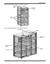
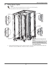
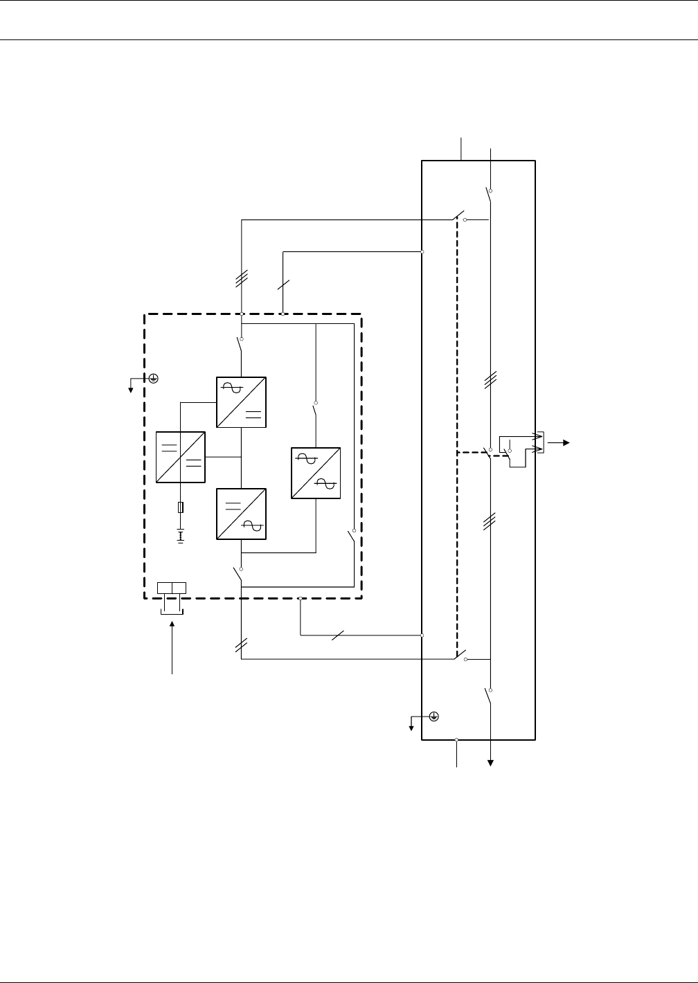
4.0 MAINTENANCE BYPASS CABINET
The Maintenance Bypass Cabinet is designed to operate in UPS mode, bypass mode and maintenance
mode. The mode is selected using the Bypass Switch.
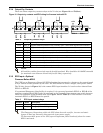
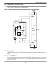
Figure 17 Single UPS with external Maintenance Bypass Cabinet—typical configuration
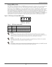
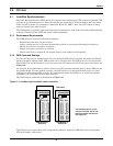
4.1 Bypass Switch
The Bypass Switch allows easy and rapid transfer of connected loads between the UPS and Bypass
source.
4.2 Normal (UPS) Mode
While the Maintenance Bypass Cabinet rotary switch is in the NORMAL position, the UPS is supply-
ing the connected load with continuous, high-quality AC power. In this mode of operation, the load is
protected by the UPS.
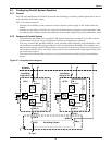
Qin UPS
Ba ttery 1
Fuse
Charger
UPS 1
CB 1
Rectifier
Static
Switch
Inverter
SW1-C
SW1-D
SW1-A
N
Input Mains
Supply A B C
N
Input Supply
A B C
N
Ext Byp
A B C
Y
Sys In CB1
Rotary
Switch
QoutUPS
Sys Out CB2
Ext Byp
CB 1
To Load
SW
N