


Installation Drawings
46
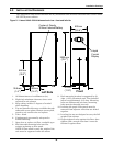
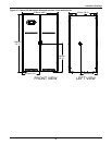
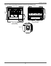
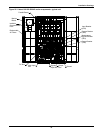
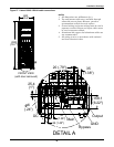
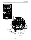
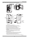
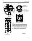
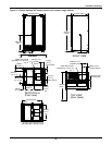
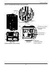
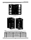
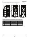
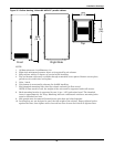
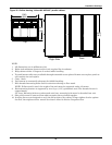
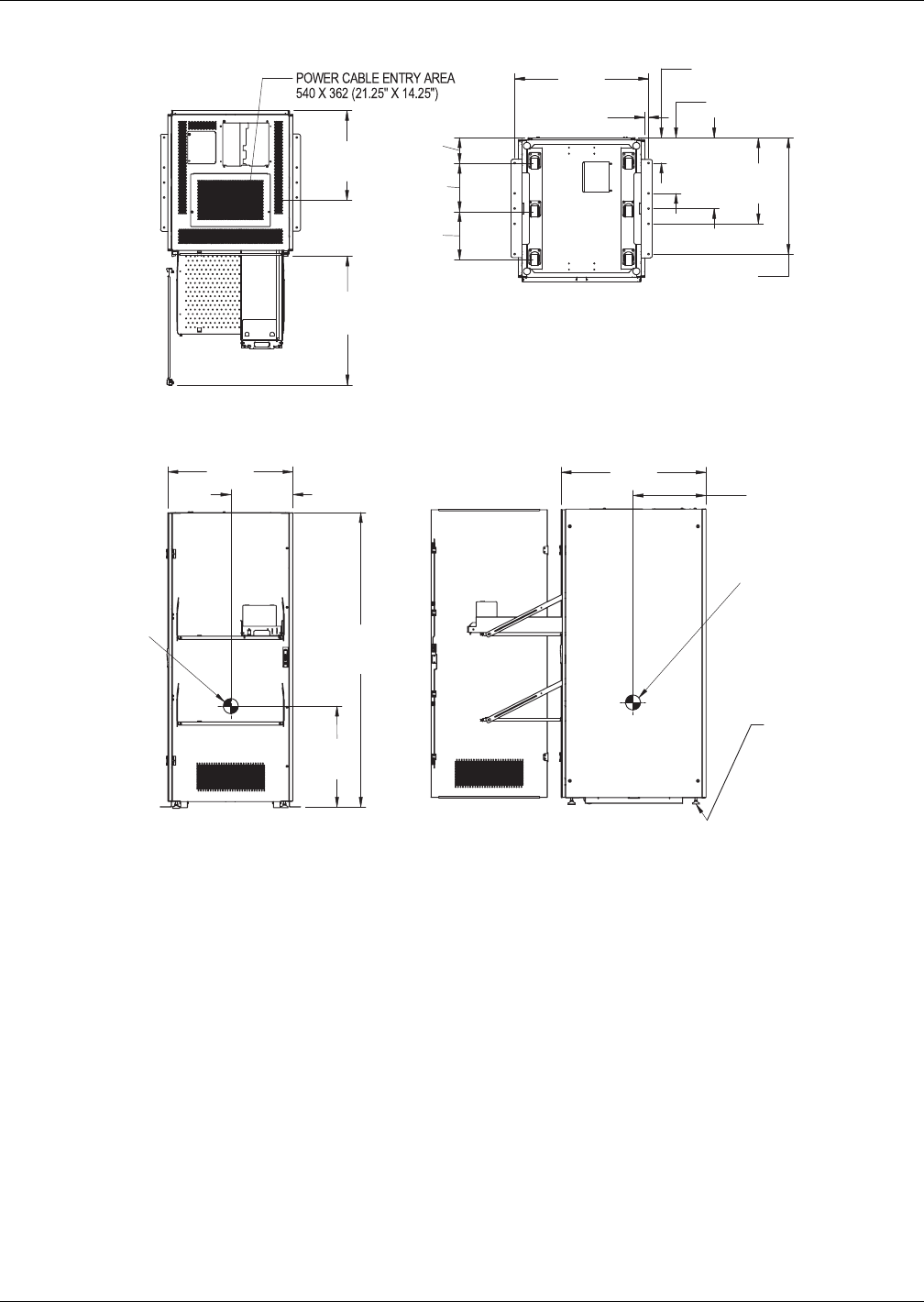
Figure 29 Outline drawing, 33" battery power pack system, single cabinet
169.5 (6.7)
372.7 (14.7)
575.9
(22.7)
779.1
(30.7)
172.1
(6.8)
965
(38)
Bottom
(Viewed From Below)
Right Side
Front
(Without Door)
Top
(Viewed From Above)
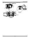
Max. Door Swing: 120°
490.3
(19.3)
896.6
(35.3)
474.3
(18.7)
26.8 (1.1)
609.3
(24)
322.9
(12.7)
322.9
(12.7)
872.2
(34.3)
845
(33.2)
418.9 (16.5)
683
(26.9)
2000
(78.7)
Leveling
Feet
(See
Note #9)
U3819204
Center
of Gravity
Center
of Gravity
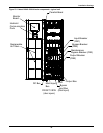
1. All dimensions are in millimeters (inches)
2. Minimum clearance 36" front and 8" top required for air exhaust.
3. Top and bottom cable entry available through removable access plates.
4. Keep cabinet within 15 deg. of vertical while handling.
5. Control wiring and power wiring must be run in separate conduit.
6. Aluminum and copper clad cables are not recommended.
7. All wiring is to be in accordance with national and local electrical codes.
8. Intercabinet wiring between the UPS and the external battery cabinet is
field-supplied.
9. Leveling feet are not designed to carry the full weight of the cabinet.
Finger-tight leveler against the floor, then tighten with a wrench less
than 2 turns for friction fit against floor.
10. Side panels included.
11. M10 threaded mounting holes used for seismic anchoring or floor stand.
NOTE: If floor stand is used the weight of the unit must be supported under
all casters. Mounting holes same spacing front and rear.
13. Battery-support tray connects to the front of the cabinet with the
support brackets. Without the support, the battery may fall out of the cabinet.