SECTION 3 BYPASSING & ISOLATING
3 --- 1
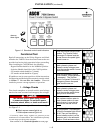
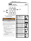
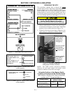
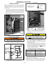
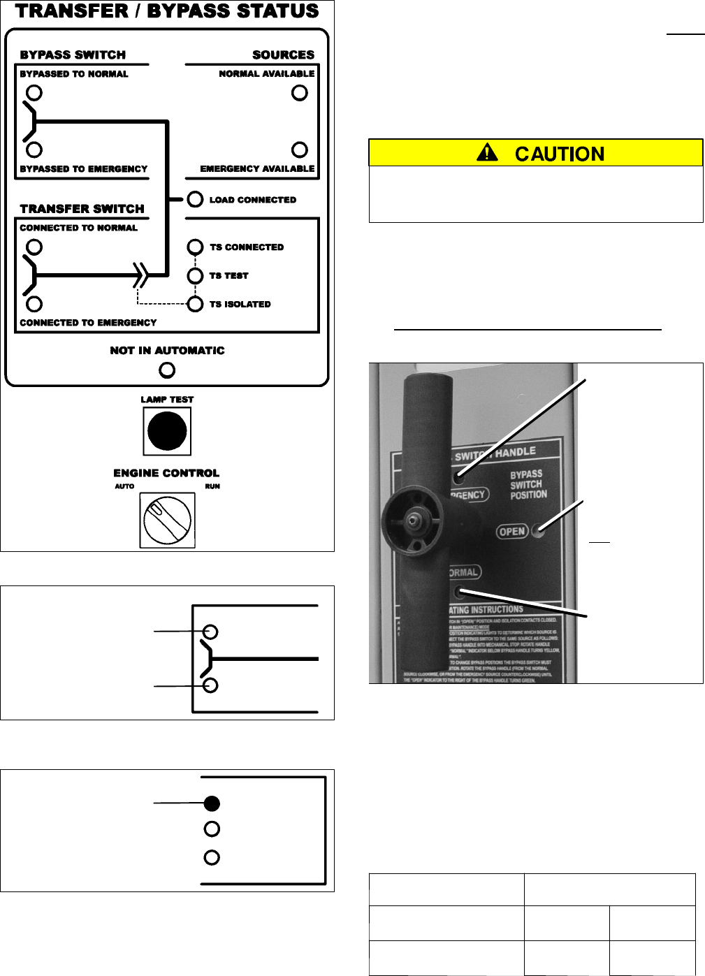
Figure 3–1. Status lights and Engine Control.
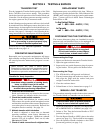
TRANSFER SWITCH
CONNECTEDTO NORMAL
CONNECTED TO EMERGENCY
Lower red light is on if
Transfer Switch is on
Emergency.
Upper green light is on
if Transfer Switch is on
Normal.
Figure 3–2. Status lights for Transfer Switch main
contact position.
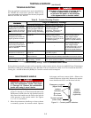
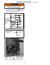
TS CONNECTEDUpper amber light
should be on.
TS TEST
TS ISOLATED
Figure 3–3. Status lights for Transfer Switch isolation
contact position.
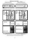
BYPASSING THE ATS*
This procedure explains how to Bypass the closed
transfer switch contacts. Bypassing is required before the
Transfer Switch can be tested or isolated. The Bypass
Switch Handle must be in the OPEN position (green
window indicator) and the Isolation Handle must be in
the CONN [connected] position (window indicator). The
TS Connected light must be on. See Figures 3–1, 3–2, 3–3.
You can only bypass to the same source
that the Transfer Switch is connected.
Solenoid interlock prevents incorrect operation.
1. Observe which Transfer Switch Connected To light is
on (Normal or Emergency) on the door. This is the
position of the transfer switch (se e Figure 3–2).
2. Follow the directions on next page to Bypass to the
same source as connected to transfer switch
(select
Normal or Emergency).
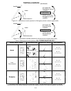
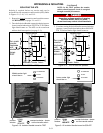
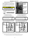
Window indicator
shows green
when the ATS is
not
bypassed.
Window indicator
shows yellow
when ATS is
bypassed to
Emergency.
Window indicator
shows yellow
when ATS is
bypassed to
Normal.
Figure 3–4. Bypass Handle and
three position window indicators.
NOTE: The 7ATB contains mechanical (window)
indicators for the bypass switch and transfer switch
positions in addition to the LED status lights.
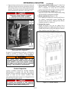
Allowable Positions of the Bypass Switch
in relation to Positions of the Transfer Switch
(with Isolation Handle in the Conn [connected]
position and TS Connected light on)
Transfer Switch
Bypass Switch
canbeineither
If Transfer Switch is in
Normal position.
Open or Normal
If Transfer Switch is in
Emergency position.
Open or Emergency


