TESTING & SERVICE
(continued)
2--3
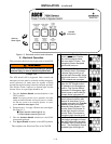
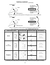
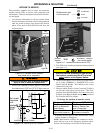
handle
shaft extension
frame
UP opens the
Emergency source
contacts
DOWN closes the
Emergency source
contacts
UPPER SHAFT
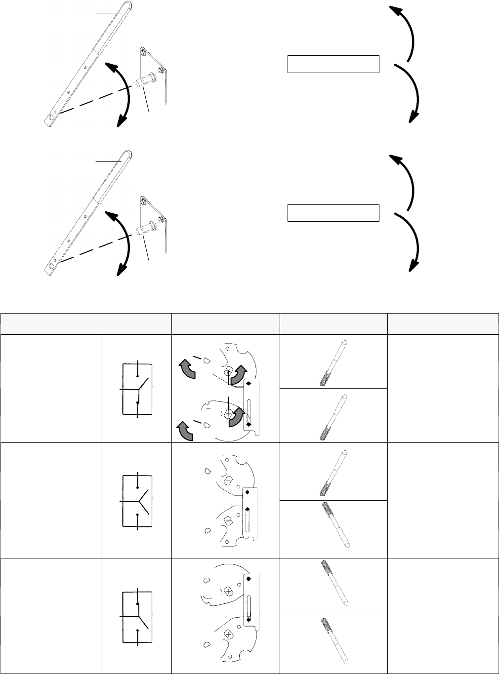
Figure 2–2. Maintenance handle operation for Emergency source contacts (upper s haft).
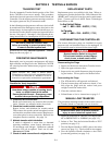
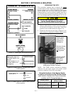
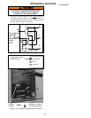
handle
shaft externsion
frame
UP closes the
Normal source
contacts
DOWN opens the
Normal source
contacts
LOWER SHAFT
Figure 2–3. Maintenance handle operation for Normal source contacts (lower shaft).
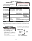
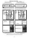
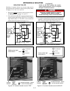
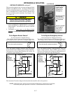
Table C. Maintenance handle positions.
ALL POWER MUST BE OFF !
Transfer Switch Position Interlocked Shafts Maintenance Handle Shaft Indicators
N
o
r
m
a
l
E
t
t
h
f
t
shaft
extension
up
E=O
upper contacts open
N
orma
l
N
link
contact sha
f
ts
shaft
extension
up
N=C
lowercontactsclosed
Load
E
up
E=O
upper contacts open
L
o
a
d
Disconnected
N
down
N=O
lowercontactsopen
E
m
e
r
g
e
n
c
y
E
down
E=C
upper contacts closed
E
mergency
N
down
N=O
lowercontactsopen
* Link between contac t shafts pr events c los ing both N and E cont acts. The s haft extensio n and co ntact s haft turn in o pposit e
directio ns thro ugh a cam–follower mec hanism. If Normal and Emergency connec tios a re revers ed this oper ation is a lso r eversed.


