


IPMC7126E/7616E I/O Module Installation and Use (6806800A45B)
Chapter 2 Installing the IPMC Module
12
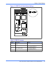
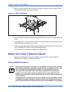
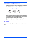
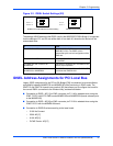
3. Remove the filler plate from the host board’s front panel. Position the IPMC module over the
center area of the slot 1 connectors as follows:
4. Line up the IPMC module’s front panel into the IPMC filler cutout slot on the host board’s front
panel.
5. Align connectors P11, P12, P13, P14, and P15 on the IPMC module with the mating connectors
on the host board and press firmly into place.
6. Insert the appropriate number of Phillips screws (typically 4) from the bottom of the host board
into the standoffs on the IPMC module and tighten the screws.
The host board is now ready to be installed into a VME chassis.
Before You Install or Remove a Board
Boards may be damaged if improperly installed or handled. Please read and follow the
guidelines in this section to protect your equipment.
Observe ESD Precautions
Use ESD
Wrist Strap
ESD
Emerson strongly recommends that you use an antistatic wrist strap and a conductive
foam pad when installing or upgrading a system. Electronic components, such as disk
drives, computer boards, and memory modules, can be extremely sensitive to
electrostatic discharge (ESD). After removing the component from its protective
wrapper or from the system, place the component flat on a grounded, static-free
surface (and, in the case of a board, component side up). Do not slide the component
over any surface.
If an ESD station is not available, you can avoid damage resulting from ESD by wearing
an antistatic wrist strap (available at electronics stores) that is attached to an active
electrical ground. Note that a system chassis may not be grounded if it is unplugged.
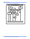
Figure 2-1. IPMC Installation