


Chapter 3 Programming
IPMC7126E/7616E I/O Module Installation and Use (6806800A45B)
17
The settings of SW2 determine the IDSEL used by the W83C553 PCI/ISA Bridge. It is important
that the settings of P1 and P2 are neither both on nor both off, otherwise the device will be
enumerated twice.
IDSEL Address Assignments for PCI Local Bus
Legacy IDSEL assignment for the PCI-to-ISA Bridge (PIB) is maintained to ensure software
compatibility between MVME2700 and MVME5100 while functioning in IPMC mode. The
IPMC712 and IPMC761 boards have a switch (S2) that allows you to configure the board for
the correct IDSEL connection to the Winbond chip, as described below:
■ Connection to IDSEL, AD[11] on PMC connector pin P11-48 is selected when using the
IPMC 712/761 with ECC VME boards MVME5100 and MVME5500 (boards released prior
to the MVME6100)
■ Connection to IDSEL, AD[16] on PMC connector pin P12-34 is selected when using the
IPMC712/761 with the MVME6100 board
■ Connection to IDSELB varies according to the base board:
– 5100: No Connect
– 5500: AD[17]
– 6100: AD[21]
– PrPMC Carrier: AD[17]
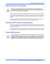
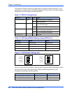
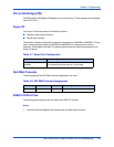
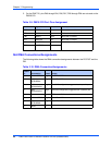
Figure 3-2. IDSEL Switch Settings (S2)
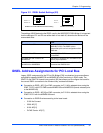
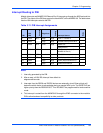
If Then
The SW2-P1 is OFF The W83C553’s IDSEL is connected to
IDSELB (P12:34). The IDSEL is then
determined by the carrier’s configuration of the
IPMC site.
The SW2-P2 is OFF The W83C553’s IDSEL is connected to AD11
on the IPMC.
The IPMC761-002 is used on an
MVME6100
The SW2-P1 should be OFF and SW2-P2 set
ON for proper operation.
The IPMC761-002 is used on an
MVME5100 or MVME5500
The SW2-P1 should be ON and SW2-P2 OFF
to emulate the IPMC761-001.
S2-P1 = 1
S2-P2 = 0
ON ON
12
12
S2-P1=0
S2-P2 =1
MVME5100 and MVME5500 S2 Default Setting
MVME6100 S2 Setting