


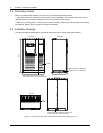
16 Chapter 3 Electrical Installation
HIPULSE U UPS Single Module And “1+N” (Expandable) 160/200/300/400kVA User Manual
3.1.3 General Notes
The following are guidelines only and superseded by local regulations and codes of practice where applicable:
1. The neutral conductor should be sized for 1.5 times the output/bypass phase current.
2. The earth conductor should be sized at 2 times the output/bypass conductor (this is dependent on the fault rating,
cable lengths, type of protection etc.).
3. Consideration should be given to the use of paralleled smaller cables for heavy currents, as this can ease
installation considerably.
4. When sizing battery cables, a maximum volt drop of 3Vdc is permissible at the current ratings given in Table 3-1.
5. In most installations, especially those concerning parallel multi-module systems, the load equipment is connected
to a distribution network of individually protected busbars fed by the UPS output rather than being connected directly
to the UPS itself. Where this is the case the UPS output cables can be rated to suit the individual distribution network
demands rather than being fully load-rated.
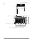
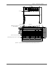
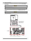
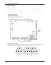
3.1.4 Cable Connections
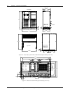
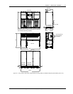
The rectifier input, bypass, output and battery power cables (all require lug type terminations) are connected to
busbars situated below the power isolator switches, as shown in Figure 3-2 and Figure 3-3.
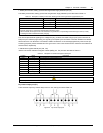
A terminal block X3 is used for connecting the control cables to the battery circuit breaker (BCB). These are female
spade type connections (fast-on 6.3*0.8) and are described later in 3.3.2 Battery Control.
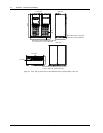
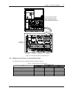
3.1.5 Safety Earth
The safety earth busbar is located near the input and output power supply connections as shown in Figure 3-2 and
Figure 3-3. The safety earth cable must be connected to the earth busbar and bonded to each cabinet in the system.
All cabinets and cable trunking should be earthed in accordance with local regulations. The earth cable should be
bound with binding strips onto the metallic column for cabling so as to prevent the fixing screw of the earth cable from
loosening in the case the earth cable is pulled.
Warning
FAILURE TO FOLLOW ADEQUATE EARTHING PROCEDURES CAN RESULT IN ELECTRIC SHOCK HAZARD TO
PERSONNEL, OR THE RISK OF FIRE, SHOULD AN EARTH FAULT OCCUR.
3.1.6 Protective Devices
For safety reasons, it is necessary to install, external to the UPS system, circuit breaking protective devices in the
input AC supply and towards the battery. Given that every installation has its own characteristics, this chapter
provides general useful information for qualified installation engineers, with knowledge of operating practices, of
regulatory standards, and of the equipment to be installed.
Rectifier and bypass input supply of the UPS
1. Protection against excessive overcurrents and short circuits in the mains supply input
These inputs must be protected, installing suitable protective devices at the distribution panel of the incoming mains
supply, considering that the protection should discriminate with overload capacity of the system (see Table 8-6 and
Table 8-7).
2. Split bypass
In the case of a split bypass being used, separate protective devices should be installed in the incoming mains
distribution panel. The protective devices must be selected for the nominal input current, with respect to the UPS
rating and the input AC supply voltage as given in Table 3-1.
3. Protection against earth faults
In the event of a residual current detector (RCD) device being installed upstream of the input supply, one must take
into account the transient and steady state earth leakage currents that are produced during start-up of the UPS.