


Chapter 3 Electrical Installation 23
HIPULSE U UPS Single Module And “1+N” (Expandable) 160/200/300/400kVA User Manual
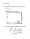
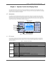
2. Intellislot intelligent communication ports
There are three intelligent communication ports (Intellislot 1, Intellislot 2, and Intellislot 3) available for installing
optional SNMP card, UPS JBUS/MODBUS adapter, and relay card.
The serial ports RS232-1, RS232-2, and the Intellislot intelligent communication ports share the same communication
resources, as described in Table 3-7.
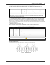
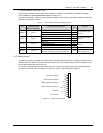
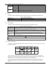
Table 3-7 Communication port resource deployment table
Port
On the UPS
LCD screen, under
Settings, controlled by:
Monitoring devices supported
Baud
rate
Comments
SNMP card 9600
JBUS/MODBUS adapter Any
Intellislot 2
Comm 1
Relay card Any
Not simultaneous with
RS232-2
SNMP card 9600
JBUS/MODBUS adapter Any
Intellislot 1
Comm 2
Relay card Any
Not simultaneous with
RS232-2
SNMP card 9600
JBUS/MODBUS adapter Any
Intellislot 3
Comm 3
Relay card Any
Not simultaneous with
RS232-2
RS232-1 Comm 1 UPSitePlusTM UPS monitoring software 9600 -
RS232-2 Comm 2
Commissioning and service software (only for use by
authorized commissioning and service personnel)
9600
Not simultaneous with the
three Intellislot ports
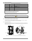
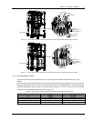
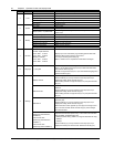
3.3.2 Battery Control
The BCB is controlled by the BCB control board. Both are located within the BCB box. This board controls the circuit
breaker's undervolts release coil and also provides a path for the circuit breaker auxiliary contacts to signal the circuit
breaker status back to the UPS control logic.
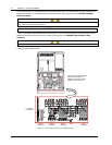
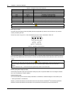
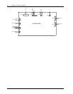
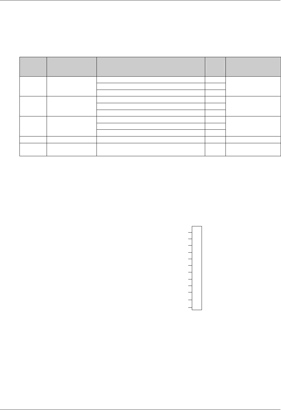
All connections between the BCB control board and the UPS module are made through the auxiliary terminal block
X3 located on the base of the UPS Cabinet. X3 is shown in Figure 3-8 and described in Table 3-8.
FB
GND
OL
+12V
TMP_T
GND
LM355+
LM355+ GND
DRV
DRV_GND
BCB status feedback
BCB connection detection
Battery temperature sensing 1
Battery temperature sensing 2
BCB drive
Not connected
NC
NC
X3
1
2
3
4
5
6
7
8
9
10
11
12
Figure 3-8 Auxiliary terminal block X3