


Chapter 6 Battery 47
HIPULSE U UPS Single Module And “1+N” (Expandable) 160/200/300/400kVA User Manual
adequate ventilation and heating of the cells. Boost charging must not be applied to valve regulated cells as this will
cause them to overcharge and subsequently vent.
Similarly, valve-regulated cells cannot be regarded as maintenance-free as they must be kept clean and their
connections checked periodically for tightness and lack of corrosion. Specific inspection instrument can also be used
to check each battery cell periodically to learn about the variation in capacity.
Batteries are fully charged before delivery; however, storage and transportation times mean that, inevitably, some
charge is lost by the time the battery is commissioned. All the cells forming the battery should be brought to the same
state of charge and be recharged within 6 months of the factory charge.
It is especially important that the battery is fully charged before attempting a witness test of the autonomy time. This
may require several days to complete; therefore any witness test concerning the batteries should take place only after
the battery has been on uninterrupted float charge for at least one week.
Cell performance typically improves after a few weeks in service or after two or three discharge and recharge cycles.
6.4 Installation Design Considerations
Note
Full safety instructions concerning the use and maintenance of UPS batteries are provided in the appropriate battery
manufacturers manuals. The battery safety information contained in this section relates to key considerations which must be taken
into account during the installation design process and might affect the design outcome depending on localized conditions.
6.5 Battery Installation And Maintenance
6.5.1 Temperature Considerations
Battery performance depends on the ambient battery temperature. Capacity and autonomy times are quoted for a
new battery operating at 20°C. Battery capacity is increased by 1% for every 1°C increase in temperature up to 25°C.
If a battery is used at temperatures above 25°C, its life is reduced; consequently its capacity and UPS autonomy time
will reduce more rapidly over a period of time. Operating below 20°C will reduce the battery capacity by
approximately 1% to 1.5% per 1°C. For example, if a battery discharge test is attempted during the middle of winter
when the ambient temperature is 5°C the battery capacity will be only 77.5% of its design value and will not satisfy its
specified autonomy time.
Ambient temperature, ventilation, spacing, float voltage and ripple current all affect the battery temperature. Uneven
temperature distribution through the battery string will cause the voltage distribution to be uneven which can also lead
to problems — it is therefore important to maintain an even temperature across the whole battery chain.
Valve-regulated cells are very sensitive to temperature and should be operated at a temperature between 15°C and
25°C. To help sustain this operating temperature range the battery is normally float charged at 2.25V/cell.
When batteries are cabinet-mounted adjacent to the UPS module, it is the battery which dictates the designed
maximum ambient temperature, not the UPS. That is, in the case of valve-regulated cells, the ambient room
temperature should be kept between 15°C and 25°C, and not between 0°C and 40°C (which is the specified main
equipment operating temperature range). Temperature excursions are permissible for short periods of time provided
the average temperature does not exceed 25°C.
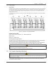
6.5.2 Battery Population
The nominal DC bus voltage, and therefore battery float voltage, is set according the module’s rated input and output
voltages, and usually set to 432Vdc (380Vac), 446Vdc (400Vac) or 459V (415Vac). Given that the desired cell float
voltage is 2.25V, this means that a different number of cells are required in each case (see Table 6-1).
Table 6-1 Battery population
Parameter 380V 400V 415V
Number of cells used (standard) 192 pcs 198 pcs 204 pcs
End-of-discharge voltage 320V 330V 340V
Float voltage 432V 446V 459V