


2 Chapter 1 General Description
HIPULSE U UPS Single Module And “1+N” (Expandable) 160/200/300/400kVA User Manual
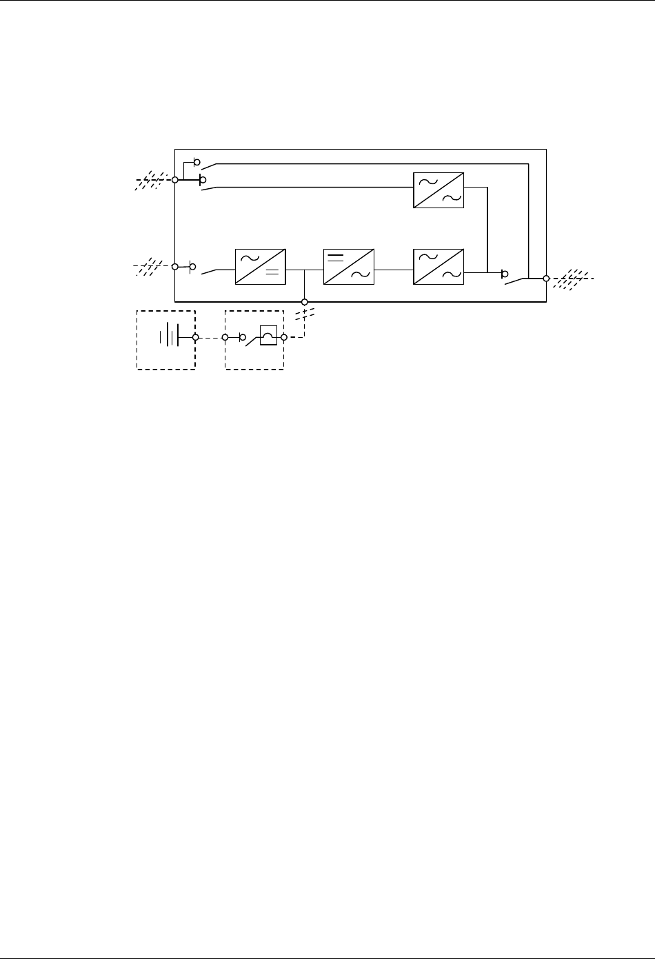
1.2.2 Bypass Supplies
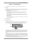
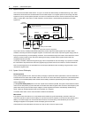
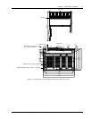
The circuit block annotated “Static switch” in Figure 1-2 contains an electronically controlled switching circuit, which
enables the critical load to be connected either to the inverter output or to a bypass power source through the static
bypass line. During normal system operation, the load is connected to the inverter, and the inverter-side of the static
switch is closed. But in the event of a UPS overload or inverter failure, it is automatically transferred to the static
bypass line.
Bypass
mains supply
Input mains
supply
Maintenance bypass switch Q3
Bypass switch Q2
Rectifier
DC bus
Input switch Q1
Battery circuit breaker
Output switch Q5
UPS output
Inverter Static switch
Battery
C.B.
UPS
Figure 1-2 UPS power switches configuration
To provide a clean (no-break) load transfer between the inverter output and static bypass line, the static switch
activates connecting the load to the bypass supplies. To achieve this, the inverter output and bypass supply must be
fully synchronized during normal operating conditions. This is achieved through the inverter control electronics, which
make the inverter frequency track that of the static bypass supply provided that the bypass remains within an
acceptable frequency window.
A manually controlled, maintenance bypass supply is also incorporated into the UPS design. Its purpose is to enable
the critical load to be powered from the mains (bypass) supply while the UPS is shut down for routine maintenance.
Note: The load equipment is not protected from normal supply aberrations when operating on bypass side or in the
maintenance bypass mode.
1.2.3 System Control Philosophy
Normal operation
During normal operation, that is, when the UPS input supply is present and within specification, both the rectifier and
inverter sections are active and the static switch is turned on to connect the inverter output to the critical load busbars.
The battery circuit breaker (BCB) is also closed and the battery is therefore permanently float charged at the DC
busbar voltage level.
(“1+N” parallel UPS system) Note: As the unit outputs are connected in parallel, the system checks that the inverter
control circuits are perfectly synchronized with one another and with the bypass mains in terms of both frequency and
phase and that they have the same output voltages. Current supplied to the load is automatically divided among
UPSs. A warning message appears while synchronization is in progress.
A module's static switch cannot close until these conditions are satisfied.
Mains failure
If the power mains has a failure or is out of tolerance the rectifier will go off automatically, while the inverter will
continue to operate on power from the battery for a period of time which depends on the load and the capacity of the
battery. If the mains supply has not returned within this time, the inverter will go off automatically and an alarm
message will appear on the operator control and display panel of the UPS.
Critical load will not be interrupted in the event of a drop or return of the AC power mains.