


36 Chapter 4 Operator Control And Display Panel
HIPULSE U UPS Single Module And “1+N” (Expandable) 160/200/300/400kVA User Manual
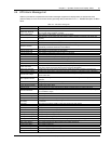
Alarm message Description
REC FLASH UPDATE Ongoing update of rectifier firmware
INV FLASH UPDATE Ongoing update of inverter firmware
MONITOR FLASH
UPDATE
Ongoing update of monitor firmware
Unit off confirm
Prompt to press the Enter key (F4) to acknowledge that the UPS will be disconnected from other
paralleled UPS modules
System off confirm
Prompt to press the Enter key (F4) to acknowledge that the all paralleled UPS will be disconnected
from the load
Fault reset FAULT CLEAR direct access key pressed
Alarm silence SILENCE ON/OFF direct access key pressed
Turn on fail
Inverter failed to turn on when INVERTER ON direct access key was pressed. This may be as a
result of Invalid Operation (Maintenance bypass on) or DC bus or rectifier not ready
Alarm reset FAULT CLEAR or SILENCE ON/OFF direct access key pressed
Transfer confirm
Prompt to press the Enter key (F4) to acknowledge that an interrupted load transfer to bypass will
happen
Transfer cancel Prompt to press the ESC key (F4) to avoid that an interrupted load transfer to bypass will happen
Manual turn on Manual Turn On through operator control and display panel
Manual turn off Manual Turn Off through operator control and display panel
Battery ground fault Battery leakage to ground detected (option)
Protocol version clash Firmware incompatibility between Monitor Board and Digital Signal Processor Board
Setting save error History records not saved. (Reserved)
Battery overtemp. The Battery temperature is over limit. Check the battery temperature and ventilation
Ambient overtemp. The Ambient temperature is over limit. Check the ventilation of UPS room
Battery fault Battery detected faulty (Reserved)
Battery maintained Battery test failed, Battery should be replaced
Battery low pre-warning
Before the end of discharge, battery undervoltage pre-warning should occur. After this pre-warning,
battery should have the capacity for 3 minutes discharging with full load. The time is user-configured
from 3 to 60 minutes. Shut down the load in time
Battery end of discharge Inverter turned off due to low battery voltage. Check the utility failure and try to recover it
Inverter comm. fail Internal RS485 communication failure between monitor and inverter
Parallel comm. fail
The CAN communication between different UPSs within a parallel system fails. 1.Check if there are
some UPSs not powered on in the parallel system. If so, power on these UPSs and check if the
alarm disappears. 2. Press the FAULT CLEAR push button
Bypass unable to trace
This alarm is triggered by an inverter software routine when the amplitude or frequency of bypass
voltage is beyond the normal range. The amplitude threshold is fixed for positive and negative 10%
rating.
This alarm automatically resets once the bypass voltage goes normal. 1. First verify that the bypass
voltage and frequency displayed on the operator control and display panel is within the selected
range. Note here the rated voltage and frequency are specified by the system voltage level and
output frequency level respectively. 2. If the displayed voltage is believed to be abnormal, then verify
the bypass voltage and frequency presented to the UPS. Check the external supply if it is found to
be faulty
Bypass abnormal
This alarm is triggered by an inverter software routine when the amplitude or frequency of bypass
voltage exceeds the limit. This alarm automatically resets once the bypass voltage goes normal.
First check if there are some relevant alarms such as Bypass disconnect open, Bypass phase
reverse. If they appear, solve them first. 1. Then verify that the bypass voltage and frequency
displayed on the operator control and display panel is within the bypass limit. Note here the rated
voltage and frequency are specified by the system voltage level and output frequency level
respectively. 2. If the displayed voltage is believed to be abnormal, then verify the bypass voltage
and frequency presented to the UPS. Check the external bypass supply if it is found to be faulty. If
the utility is likely to trigger this alarm frequently, the bypass limit can be changed a little larger
through the configuration software according to the customer’s agreement
Inverter asynchronous
This alarm is triggered by an inverter software routine when the inverter and bypass waveforms are
misaligned by more than 6 degrees in phase. This alarm resets automatically once the condition is
no longer true. 1. First check if the alarm Bypass unable to trace or Bypass abnormal occurs. If so,
solve it first.
2. Verify the waveform of the bypass voltage. If it is too distorted, ask the customer to verify and seek
any possible measurements
Inverter output abnormal Inverter output voltage beyond limits. Load transfers to bypass