


PIP-ControlWaveLS Page - 3
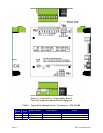
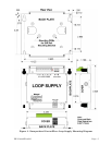
8-Pin Connector (TB2) accommodates distribution of the regulated +24V loop supplies.
Table 2 - Regulated 24V Supply Distribution Connector TB2
TB2 Pin # Signal Name Description
1, 3, 5, 7 +24V Regulated +24Vdc
2, 4, 6, 8 24V Return Reg. 24V Return
• Configuration Jumper JP1
Jumper JP1 is used to set the input voltage range, i.e., 9V to 30V (nominal 12V input) or
19V to 30V (nominal 24V input). Under Voltage Lockout Point circuitry sources current to
affectively lower the ON and OFF switch points.
The nominal setting operating range switch points for the Loop Supply (by design) are
provided below.
JP1 - 1 to 2: 12V Input: ON above 8.4V (Max. ON = 8.8V), OFF below 8.24V (Min. OFF =
7.8V) (Factory Configuration)
JP1 - 2 to 3: 24V Input: ON above 18.8V, (Max. ON = 19.7V), OFF below 18.4V (Min. OFF
= 17.4V
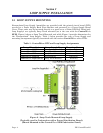
• Power LED
Red LED (CR10) will be ON when regulated 24V is present. When lit, CR10 indicates that
the Loop Supply is operational.
• Fuse F1
Fuse F1 (2A Slow Blow 5 x 20 mm) provides protection for the LOOP Supply and the as-
sociated field I/O (powered by Loop Supply). If a short circuit should occur in I/O field
wiring or circuitry within the Loop Supply, F1 will blow and the regulated 24V output will
switch OFF. Note: Power Pass-through is not fused since the ControlWave
GFCs/RTUs provide their own fuse protection.