


Page - 6 PIP-ControlWaveLS
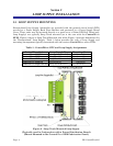
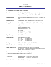
2.2 LOOP SUPPLY WIRING
Loop Supply’s utilize Terminal Blocks that are equipped with compression-type terminals
which accommodate a #16 AWG size wire. A connection is made by inserting the wire’s
bared end (1/4” Max.) into the clamp beneath the screw and then tightening the screw.
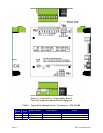
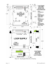
Three Loop Supply Terminal Blocks accommodate wiring as follows:
TB1 – Typically interfaces Bulk Power Input (May be used for Bulk Power Pass-through)
TB1-1 – VIN (9-30V Bulk Power Input)
TB1-2 – GND (9-30V Bulk Power Return)
TB1-3 – EARTH (CHASSIS Ground)
TB2 – 24Vdc Loop Power
TB2-1, 3, 5, 7 – 24V (Regulated +24V)
TB2-2, 4, 6, 8 – 24VRET (Regulated 24V Return)
TB3 – Typically interfaces Bulk Power Pass-through (May be used for Bulk Power Input)
TB3-1 – EARTH (CHASSIS Ground)
TB3-2 – GND (9-30V Bulk Power Return)
TB3-3 – VIN (9-30V Bulk Power Input)
Field I/O Wiring Considerations
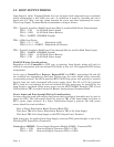
Regardless of the ControlWave RTU type in question, Loop Supply wiring will only be
utilized in conjunction with non-isolated I//O. Refer to Fig. 4 or 5 for applicable RTU wiring
assignments.
In the case of ControlWave Express, ExpressPAC and GFCs, non-isolated AI and AO
are available but, depending on the Input Voltage type, the unit’s AI/AO will be internally
or externally powered. For 24Vdc powered RTUs AI/AO loop power will typically be sourced
directly from the unit’s associated bulk power supply input. For 6V or 12V (dc) powered
RTUs, both the non-isolated AI and non-isolated AO loop power may be provided by the
Loop Supply’s regulated 24Vdc power output via the EXT POWER Terminal (TB7-3) and
GND terminal (TB7-4) on the Process I/O Board’s Analog Output Terminal Block.
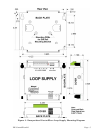
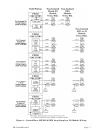
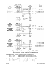
Power Input and Pass-through Wiring Considerations
In some cases the same bulk supply that powers the Loop Supply Assembly may be used to
power the RTU. The bulk source should be wired to TB1 of the Loop Supply and then to
RTU’s power input terminal. If a Power Distribution Board is present, the bulk power
source should be wired as follows:
First to Power Distribution Board Terminal Block TB1
Then from TB2 of the Power Distribution Board to TB1 of the Loop Supply
Then from TB3 of the Loop Supply to the RTU’s Input Power Terminal.
Bulk power may be supplied from Loop Supply connector TB3 (pass-through) to one of the
following RTU Input Power Terminals):
Controlwave MICRO – Power Supply/Sequencer Module (PSSM) - Connector TB1
TB1-1 = +VIN (from loop Supply Connector TB3-3 = VIN)
TB1-2 = -VIN (from loop Supply Connector TB3-2 = GND)