2103 Modem Module
Section 3 2103C Cellular Modem Module
3-3
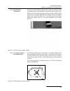
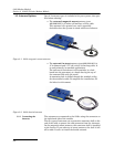
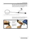
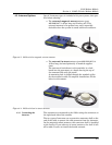
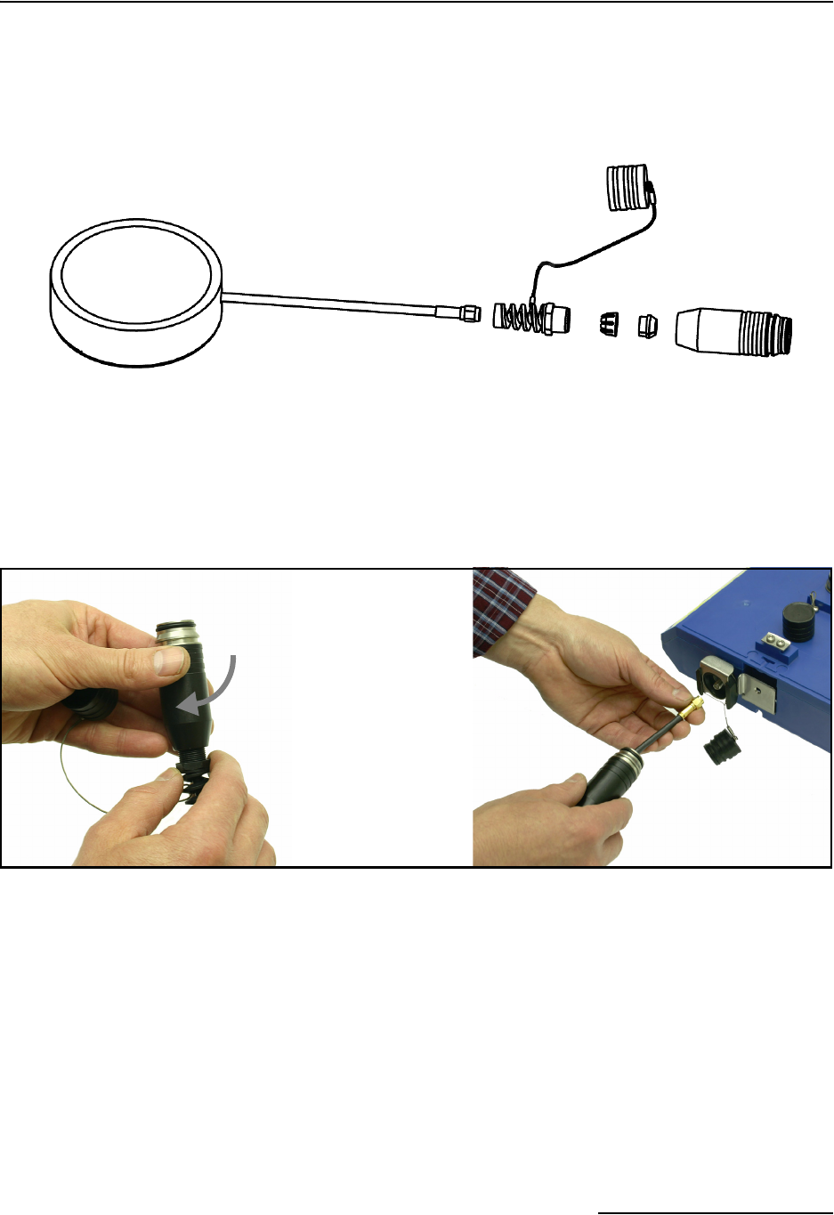
When you are ready to connect the in-street antenna to the
2103
C modem, you will need to assemble the connector shell onto
the end of the cable. The pieces of the connector shell are shown
in Figure 3-3. An instruction sheet (P/N 60-2003506) is shipped
with the antenna, and shows you the assembly steps.
Figure 3-3 Protective connector shell pieces for the in-street antenna
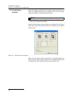
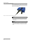
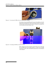
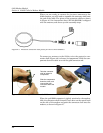
To connect an antenna to the 2103
C, twist the protective con-
nector shell (Figure 3-4) to loosen its components. Slide the com-
ponents down the cable to reveal the gold connector end.
Figure 3-4 Connecting an antenna to the 2103
C
Twist the connector
shell to loosen its
components.
Slide the components
down the cable, and
connect the gold
connector end to the
modem.


