


Connecting to the Network
3-6 Installation
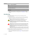
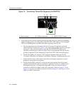
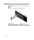
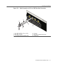
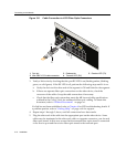
Figure 3-4 Connecting a Twisted Pair Segment to the 2G4072-52
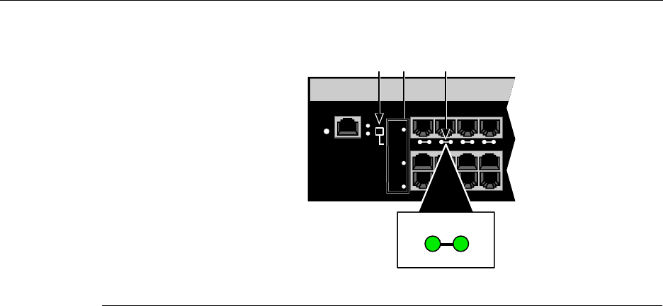
3. VerifythatalinkexistsbycheckingthattheportRX(Receive)LEDisON(flashing
amber,blinkinggreen,orsolidgreen).IftheRXLEDisOFFandtheTX(Transmit)
LEDisnotblinkingamber,performthefollowingstepsuntilitison:
a. Toviewthereceiveandtransmit
activityonagroupofsegments,pressthe
GROUPSELECTbutton(seeFigure 3‐4)tosteptothegroupofinterest(Groups1
through3).Eachtimethebuttonispressed,theGROUPLEDlightsupin
sequence,indicatingthe selectedGroup.Receiveandtransmitactivityforthat
groupof
segmentsisthenindicatedbytheRXandTXLEDsforeachsegment.
b. VerifythatcablingisCategory5UTPwithanimpedancebetween85and
111 ohms. Iftheportistooperateat100 Mbps,Category 5cablingmustbeused.
c. Verifythatthedeviceattheotherendofthetwisted
pairsegmentisonand
properlyconnectedtothesegment.
d. VerifythattheRJ45connectorsonthetwistedpairsegmenthavetheproper
pinoutsandcheckthecableforcontinuity.Typically ,acrossovercableisused
betweenhubdevices.Astraight‐throughcableisusedtoconnectbetween
switchesorhub
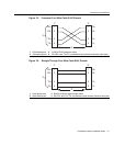
devicesandanenduser(computer).RefertoFigure 3‐5and
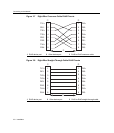
Figure 3‐6forfour‐wireRJ45connections.RefertoFigure 3‐7andFigure 3‐8for
eight‐wireRJ45connections.
1 RJ45 connector 2 RJ45 port connector 3 GROUP SELECT button
RESET
CONSOLE
CPU
PWR
GROUP
SELECT
GROUP 3
GROUP 2
GROUP 1
1
2
3
4
À ÂÁ
2
TX
RX