


Index-2
Mode Switch
setting of B-2
Module features 1-2
N
Network
connecting to 3-5
Network Requirements
list of 2-1
P
Pinout assignments
console port A-6
Pinouts
crossover 3-7, 3-8
straight-through 3-7, 3-8
Power connection 3-4
R
Receive LEDs
viewing of 4-1
Regulatory Compliance A-6
Related manuals
obtaining xvi
Required Tools B-2
S
Safety requirements A-6
Shutdown
last resort 4-6
overview 4-5
Using RESET Button 4-6
SIMMs
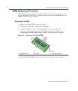
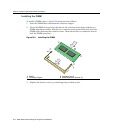
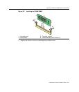
installing DIMM B-6
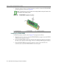
Installing the DRAM SIMM B-8
location B-4
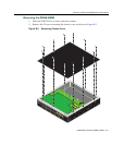
Removing the DRAM SIMM B-7
Specifications A-1
Mini-GBICs A-2
Specifications, MGBIC-08 A-5
Specifications, MGBIC-LC01
operating range A-3
optical A-3, A-5
Specifications, MGBIC-LC09
operating range A-4, A-5
optical A-4, A-5
Specifications, MGBIC-MT01
operating range A-3
optical A-3
Standards compatibility 1-3
T
Technical support
contacting Enterasys for xviii
Transmit LEDs
viewing of 4-1
Troubleshooting 4-1
checklist for 4-4
U
Unpacking the module 3-1
V
Viewing Receive and Transmit Activity
instructions for 4-1
W
WebView
introduction to 1-2