


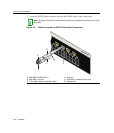


Connecting to the Network
3-12 Installation
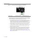
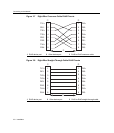
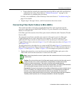
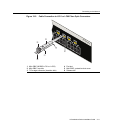
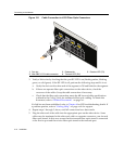
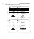
Figure 3-11 Cable Connection to LC03 Fiber-Optic Connectors
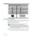
3. VerifyalinkexistsbycheckingthattheportRXLEDison(flashingamber,blinking
green,orsolidgreen).IftheRXLEDisoff,performthefollowingstepsuntilitison:
a. VerifythedeviceattheotherendofthesegmentisONandlinkedtothesegment.
b. Ifthereareseparatefiber‐opticconnectionsontheotherdevice,checkthe
crossoverofthecables.Swapthecableconnectionsifnecessary.
c. Checkthatthefiber‐opticconnectionmeetsthedBlossand cablespecifications
outlinedintheCablingGuideformultimodefiber‐opticcabling.Toobtainthis
document,refer
to“RelatedDocuments”onpage xvi.
Ifalinkhasnotbeenestablished,refertoChapter 4forLEDtroubleshootingdetails.If
aproblempersists,referto“GettingHelp”onpage xviiiforsupport.
4. Repeatsteps1through3,above,untilallconnectionshavebeenmade.
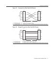
5. Plugtheotherendofthecableintothe
appropriateportontheotherdevice.Some
cablesmaybeterminatedattheother endwithtwoseparateconnectors,oneforeach
fiber‐opticstrand.Inthiscase,ensurethatthetransmitfiber‐opticstrandisconnected
tothereceiveportandthereceivefiber‐opticstrandtothetransmitport.
1 Port slot 3 Release tab 5 Receive LED (TX)
2 Mini-GBIC-LC03 cable connector 4 Transmit LED (RX)
13 14 15 16 17 18 19 20
Á
2G4072-52
Â
À
Ä
Ã