


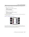
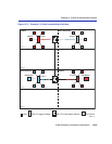
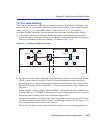
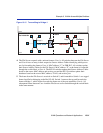

Example 2, VLANs Across Multiple Switches
VLAN Operation and Network Applications 13-27
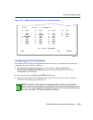
4. Port 4 is configured as a trunk port by setting the Egress type for both VLAN ID 2, Port 4 and
VLAN ID 3, Port 4 to TAGGED using the Static VLAN Egress Configuration screen. This
means that these ports will only transmit tagged VLAN frames.
• Port 4, Egress: TAGGED
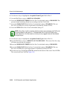
5. Port 4 is configured as follows using the VLAN Port Configuration screen:
• Port 4 is set as follows:
PVID: 1
Acceptable Frame Types: ADMIT TAGGED FRAMES ONLY
Ingress Filtering: ENABLED
GVRP Status: ENABLED
Port 4 is set as a trunk port and all frames forwarded out this port are forwarded as tagged frames.
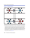
By default the port remains as a member of the Default VLAN. With the original classification
information inserted in the frame Tag Header, the receiving switch will maintain the original
frame classification. GVRP is enabled on this port and will support dynamic VLANs created by
GVRP.
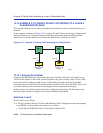
Switch 2
Switch 2 is set as follows:
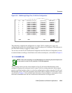
1. Two VLANs are added to the list of VLANs in the Static VLAN Configuration screen. An
FDB ID is automatically assigned to each VLAN. In this example, the following VLANs are
created:
• VLAN ID 2, FDB ID 2, with a VLAN Name of Red
• VLAN ID 3, FDB ID 3, with a VLAN Name of Blue
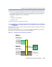
2. The Egress type for both VLAN ID 3, Port 1, and VLAN ID 2, Port 3, are set to UNTAGGED
using the Static VLAN Egress Configuration screen. This means that these ports will transmit
only untagged VLAN frames.
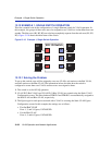
3. Ports 1 and 3 are configured as follows using the VLAN Port Configuration screen:
• Port 1 is set as follows:
PVID: 3
Acceptable Frame Types: ADMIT ALL FRAMES
Ingress Filtering: ENABLED
GVRP Status: DISABLED