


Example 3, Filtering Traffic According to a Layer 4 Classification Rule
13-32 VLAN Operation and Network Applications
13.14 EXAMPLE 3, FILTERING TRAFFIC ACCORDING TO A LAYER 4
CLASSIFICATION RULE
This example illustrates how to filter out broadcast transmissions at Layer 4 from other parts of a
network.
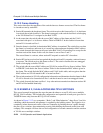
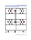
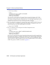
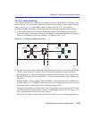
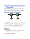
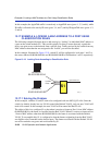
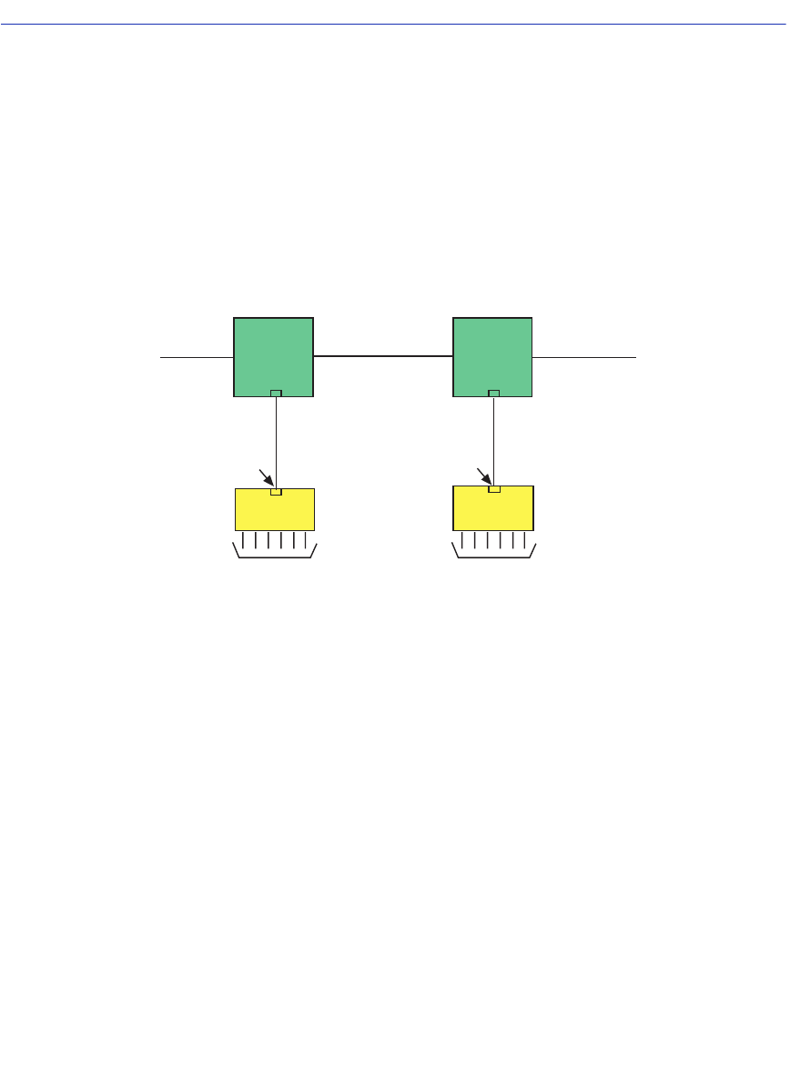
In this example, illustrated in Figure 13-16, switches S1 and S2 have already been configured and
operating. However, it was discovered that the Routing Information Protocol (RIP) broadcast
frames from routers R1 and R2 were flooding the subnetwork of Switches S1 and S2.
Figure 13-16 Example 5, Filtering Traffic According to a Classification
13.14.1 Solving the Problem
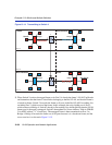
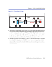
To prevent the RIP broadcasts from flooding the users’ terminals connected to S1 and S2, a new
VLAN will be added to each switch, but not assigned to any ports (creating a Null VLAN). Then
each switch will be configured with a Layer 4 classification rule that will classify each RIP
broadcast frame received on Port 25 of each switch to the Null VLAN. Since the Null VLAN is not
associated with any ports, the frame will be dropped and not transmitted out any port.
In this example, the switches have already been configured and operating. The following covers
only those steps needed to configure each switch to eliminate the problem.
Switches 1 and 2
Each switch is set as follows:
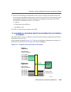
1. A VLAN is added to the list of VLANs in the Module/VLAN Configuration screen and assigned
to an FDB ID. In this example, the switch is set as follows:
• VLAN ID 99, FDB ID 99, with a VLAN Name of Null VLAN
2599_27
Users Users
R2
R1
Port 25 Port 25
S1
S2