


DFE Module Placement and Installation Rules
3-4 Installation
Toensureproperoperationofthesystem,considerthefollowingexamplesandrulesfor
moduleplacementineitherchassis.
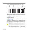
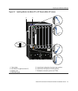
Example 1 (Figure 3-1, A)
Showsonemoduleinstalledinthechassis.Ifthechassisispopulatedwithonlyone
4xxxxx,itmustbeinstalledinslot1.
Rule:Ifonlyone4xxxxxisinstalledinthechassis,itmust beinslot1.Alwaysinstalla
4xxxxxinslot1ofthechassis.
Example 2 (Figure 3-1, B)
Showsthechassisfullypopulatedwith4xxxxxmodules.Bydefault,thechassissystem
cancontinuetooperateafterlosingoperationofallmodulesexceptthemoduleinslot1.
(Thelossofoperationcanbeduetomodulereset,removal,orfailure.)However,withthe
redundancykeyinstalled,thesystemwill
remainoperationalprovidedthatthereisan
operatingmoduleinslot1or2.
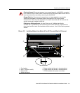
Figure 3-1 Examples, Slot Numbers/Module Placement in Matrix E7 or N7
Caution: When installing a module into slot 1 of a non-operating chassis, it is strongly
recommended that the module have the desired version of firmware. Installation of a
replacement module into slot 1 of a non-operating chassis requires reconfiguration of the
system settings.
Precaución: Para instalar un módulo en la ranura 1 del chasis apagado, lo mejor es que
el módulo corresponda a la versión de firmware solicitada. Para instalar un módulo de
reemplazo en la ranura 1 del chasis apagado será necesario reconfigurar el sistema.
4XXXXX
1 2 3 4 5 6 7
4XXXXX
7XXXXX
1 2 3 4 5 6 7
4XXXXX
1 2 3 4 5 6 7
1 2 3 4 5 6 7
4XXXXX
A DCB