


Connecting to the Network
Matrix DFE-Gold Series PoE Module 4H4285-49 Installation Guide 3-17
f. EnsurethatthetwistedpairconnectionmeetsthedBlossandcablespecifications
outlinedintheCablingGuide.Referto“RelatedDocuments”onpage xvifor
informationonobtainingthisdocument.
IfalinkisnotestablishedanditisconnectedtoaPDdevice,checkthePoEPort
Statusto
ensurethatthereis48Vdcpoweratthe4H4285‐49RJ45port.Referto
“VerifyingPoEPortStatus”onpage 3‐17.Ifthereisstillaproblem,contact
EnterasysNetworks.Referto“GettingHelp”onpage xviiifordetails.
4. Repeatsteps1through3above,untilallconnectionshavebeenmade.
Verifying PoE Port Status
IfaPDisconnectedtothe4H4285‐49RJ45port,ensurethatthereispowerattheRJ45port
asfollows:
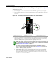
1. PressontheGROUPSELECTbuttonformorethanonesecond.The4H4285‐49will
enterthePoEstatusmode,whichwillindicateasetofpowerstatusconditions
relatingtothePoEPortStat us.
2. Now,everytimeyoupresstheGROUPSELECTbuttonforlessthanasecond,the
GROUPLEDlightsupinsequence,indicatingwhichGroupisselected.ThePoE
POWERSTATUSforthatgroupofsegmentsisthenindicatedbytheRXandTXLEDs
for
eachsegment.Ifthereispowerattheport,theRXLEDisgreenandtheTXLEDis
off.Otherwise,refertoChapter 4fortroubleshootinginformation.
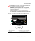
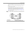
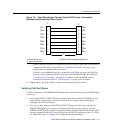
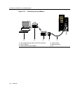
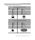
Figure 3-8 Eight-Wire Straight-Through Cable RJ45 Pinouts, Connections
Between Switches and End-User Devices
1 RJ45 device port 3 RJ45-to-RJ45 straight-through cable
2 Other device port
TX1+
TX2+
RX4-
RX1-
TX4+
RX3-
TX3+
RX2-
2
1
3
6
4
5
7
8
TX2+
TX1+
RX3-
RX2-
TX3+
RX4-
TX4+
RX1-
2
1
3
6
4
5
7
8
Â
À
Á