


2-1
Chapter 2
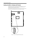
Installing the 9E312-12 Module
The 9E312-12 module occupies two slots in the MMAC-Plus chassis. The module
must be installed with the left side (as viewed from the front) in an odd numbered
slot, and the right side in an even numbered slot.
To install the 9E312-12 module, follow the steps below:
1. Remove the blank panels, covering the slots in which the module will be
mounted. All other slots must be covered to ensure proper airflow and
cooling.
2. Carefully remove the module from the shipping box. (Save the box and
packing materials in the event the module must be reshipped.)
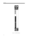
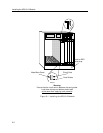
3. Attach one end of the ESD wrist strap packaged with the MMAC-Plus chassis
to your wrist. Plug the other end into the jack for the ESD Wrist Strap in the
lower right corner of the MMAC-Plus Chassis shown in Figure 2-1.
4. Remove the module from the plastic bag. Observe all precautions to prevent
damage from Electrostatic Discharge (ESD).
5. Carefully examine the module, checking for damage. If any damage exists,
DO NOT install the module. Contact Cabletron Systems Technical Support
immediately.
6. Install the module into the chassis by sliding it into slots and locking down
both the top and bottom plastic tabs, as shown in Figure 2-1. Take care that
the module slides in straight and engages the backplane connectors properly.
When installing the module, ensure that both circuit cards are between the
card guides, as shown in Figure 2-1. Check both the upper and lower tracks of
both cards.
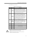
The INB Terminator Modules must be installed on the rear of the chassis before powering
up this module. Refer to the INB Terminator Modules Installation Guide for
information and installation procedure.
NOTE