


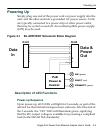

Powering Up
2-4 Installation and Connection
Detection Sequence
OnceacompliantloadisattachedtotheoutputRJ45connector,
thegreen“CONNECT”LEDwillilluminate.
Shouldtheloadbenon‐compliant,thentheLEDswillblinka
codesignifyingthecausefornon‐detection.
Detection Failure Codes
1. Incorrectresistivesignature–Thegreen“CONNECT”and
red“FAULT”LEDswillblink3times.
2. Incorrectcapacitivesignature–Thegreen“ON”LEDwill
blink3times.
3. IncorrectVoffset–Thegreen“CONNECT”andgreen“ON”
LEDswillblink3times.
4. Unstablecurrentmeasurement–Thegreen“ON”LEDwill
blink3times.
5. Lowvoltagesensedduringdetection(overload)–Thered
“FAULT”LEDwillblink3
times.
AftertheLEDsblink3timestheBL‐69551ENTwillcontinueto
trytodetectavalidload.Therefore,untilthecorrectloadis
applied,theLEDswillcontinuetoblink.Ifthereisanopen
circuitconnectedtotheoutputRJ45,thentheLEDswillnotblink
butthe
BL‐69551ENTwillcontinuetotrytodetectavalidload.
Fault Sequence
Shouldtherebeafaultsuchasanoverloadorshortcircuit,then
thered“FAULT”LEDwillilluminate.Thered“FAULT”LED
willilluminatefor2secondsandthengooffasthepowersupply
triestore‐detect
avalidload.Ifthereisaproblemindetecting,
theLEDwillindicatewhatiswrongwiththeloadasperthe
codesinthesectionabove.