


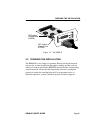

CONNECTING THE BRIM TO THE NETWORK
BRIM-E6 USER’S GUIDE Page 17
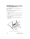
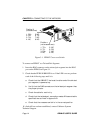
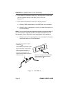
3. Attach the fiber labeled 2 to the applicable transmit port labeled TX,
on the module.
4. At the other end of the fiber optic cable, attach the fiber labeled 1 to
the transmit port of the device.
5. Attach the fiber labeled 2 to the receive port.
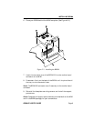
6. Check that the EPIM’s LNK LED is on. If the LED is not on, perform
the following steps until it is:
a. Check that the power is turned on for the device at the other
end of the link.
b. Verify proper “receive to transmit” connection of fiber strands
between the applicable port on the module and the fiber optic
device at the other end of the fiber optic link segment.
c. Verify that the fiber connection meets the dB loss specifications
outlined in Appendix B.
If a link still has not been established, contact Cabletron Systems
Technical Support.
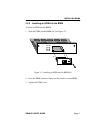
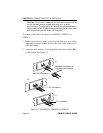
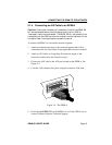
3.1.3 Connecting a Thin-Net Segment to an EPIM-C
To connect a thin-net segment to an EPIM-C, refer to Figure 3-3 and
perform the following steps:
1. Set the Internal Termination Switch to the right of the port and labeled
TERM to:
• The on position (•) if the thin-net segment connected directly to the
port will be internally terminated at the port.
• The off position (o) if the thin-net segment will not be terminated at
the port or externally terminated.