


Preparation
Page 2 of 5 PN 9033946
Preparation
The DIMM is located on the main pc board assembly of the DFE Series Module. In some cases,
depending on the module to be upgraded, it may be necessary to remove a daughter board to gain
access to the existing DIMM. For information about the location and instructions to gain access to
the DIMM, refer to the associated DFE Series Module installation guide.
Before installing the DIMM, proceed as follows:
1. Notify the system administrator before starting any work on the system.
2. If the DFE module is already installed in an E7, N7, or N3 chassis, disconnect any attached
cables, then remove it from the chassis.
3. Place the DFE module on a flat non-static surface with the main board facing upward.
4. Locate the DIMM to be replaced on the main board.
5. If the DIMM is under a daughter board, refer to the module installation guide for instructions
to remove the daughter board. To replace a DIMM, proceed to “DIMM Replacement
Procedure” below.
Caution: To prevent damage from static discharge, use an antistatic wrist strap, and observe all
static precautions during this procedure. Failure to do so could result in damage to the DIMM,
module, or both.
9
Tip: Before performing step 2, mark the cables connected to the DFE Series Module according to
their associated port numbers. This is recommended for ease of reinstallation.
Note: If you are not familiar with the DFE module removal and installation procedures, refer to the
associated module installation guide.
Note: Depending on the DFE series module being upgraded, the daughter board may not be a
field-replaceable part. Refer to the associated DFE series module installation guide to determine if
the daughter board is a field-replaceable part.
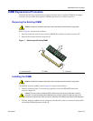
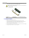
There are two types of DIMM connectors used on the DFE series module. Depending on the
module, the DIMM is installed either at an angle or vertically. The replacement procedure in this
document applies to both types.