


Completing the Installation
Page 4 of 5 PN 9033946
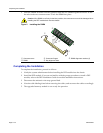
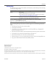
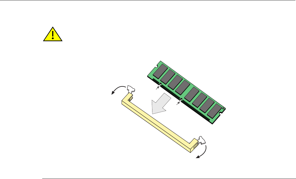
3. Push the DIMM ➁ further into the connector until the two DIMM alignment notches ➄ and
the tabs on the two connector arms
➀ lock the DIMM into place.
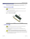
Figure 2 Installing the DIMM
Completing the Installation
To complete the installation, proceed as follows:
1. Notify the system administrator before installing the DFE module into the chassis.
2. Install the DFE module. If you are not familiar with the proper procedure to install a DFE
module, refer to the DFE Installation Guide for module installation instructions.
3. Disconnect the antistatic wrist strap ground lead.
4. Note the cable labeling done before removing the cables, and reconnect the cables accordingly.
5. The upgraded memory module is now ready for operation.
Caution: If the DIMM is not firmly locked into position, the connector arms could be damaged when
installing the DFE module back into the chassis.
➀
Connector arms
➂
Connector fingers
➄
DIMM alignment notches (2)
➁
DIMM
➃
Key alignment slots
Ä
Ä
Â
À
À
Á
Ã
Ã