


DM-D110/D210 User’s Manual 1
English
English
DM-D110/D210
User’s Manual
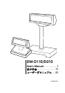
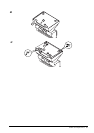
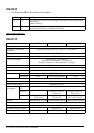
Illustrations
All of the illustrations are at the beginning of this manual. They are identified by letters (A, B, C . . .). Some
of the illustrations have numbers in them. See the list below for the meaning of the numbers.
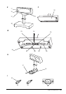
Illustration A: Illustration E: Illustration I:
1. Screen 17. Screen 33. Grooves (1 or more)
2. DM-D110 18. DM-D210 34. Inch Screws
3. DIP switch (rear side of the
display)
19. POWER Switch (rear side of the
display)
35. Metric Screws
36. Screw for Attaching the
RS-232 Connector
4. POWER switch (bottom of the
display)
20. Stand (DP-210)
21. DIP Switch (bottom of the
display)
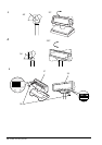
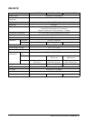
Illustration L:
5. Stand (DP-110) 37. DM-D110
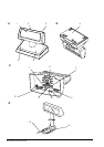
Illustration B: Illustration F: 38. DM-D210
6. Plate 22. Plate 39. DIP switch
Illustration C: Illustration G:
7. Power Supply Connector 23. Power Supply Connector
8. DM-D110 Cable 24. DM-D210 Cable
9. Power Supply Extension Cable
Connector
25. Power Supply Extension Cable
Connector
10. PC Connector 26. PC Connector
11. DM-D110 Connector 27. DM-D210 Connector
12. JP1 28. JP1
13. JP2 29. JP2
14. Printer Connector 30. Printer Connector
Illustration D: Illustration H:
15. Connection to the DM-D110
Cable Printer
31. Connection to the DM-D210
Printer Cable
16. DP-502 32. DP-502