


S5U1C63000H2 MANUAL EPSON 13
(S1C63 FAMILY IN-CIRCUIT EMULATOR)
CHAPTER 5: OPERATION AND FUNCTION OF S5U1C63000H2
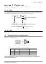
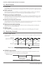
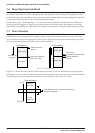
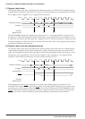
● TRCIN input terminal
By connecting a signal line of the target system to this terminal, trace information is stored into the
trace memory. "1" is written to the trace memory when it is not connected or the signal is at high level,
and "0" is written to the trace memory when the signal is at low level. The signal is sampled at the
rising edge of T4 state.
● BRKIN input terminal
A break occurs when a low level signal is input to this terminal while the target program is running.
To use this terminal for the break function , the low level pulse must be 20 msec or longer. By connect-
ing the TRGOUT output terminal to the BRKIN input terminal, breaks can be occur according to the
trace trigger conditions.
5.4 Display During Execution and During Break
The S5U1C63000H2 control processor monitors the execution status of the S1C63000 CPU while the target
program is running. It displays the S1C63000 CPU’s execution status in every 500 msec when the on-the-
fly display mode is specified. Program counter value that are displayed during break show the address to
be executed in next step. Values in all registers are at the time of the break.
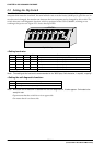
The LED’s (PC15–PC0) on the front panel indicate the executed program counter value during execution,
and stops at the break address when a break occurs.
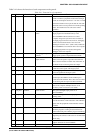
5.5 Break Commands
The S5U1C63000H2 has abundant break functions.
(1) PC break
This break function is specified by the BP command. When the program counter of the S1C63000 CPU
coincides with the specified address, a break occurs before executing the instruction. Multiple PC
values (up to maximum size of program memory) can be specified as break points.
(2) PC sequential break
This break function is specified by the BS command. The break occurs when the PC of the S1C63000
CPU counts three addresses in specified order. The pass count can be specified for the last address.
The sequence (address 1 coincidence) → (address 2 coincidence) → (address 3 counted by specified
times) breaks the execution.
(3) Break by data access
This break function is specified by the BD command. The break occurs immediately after the target
program accesses the data memory in the specified condition (AND condition of address, data and
read/write operation). It is possible to specify a range for the address condition, a mask in bit units
for the data condition and a mask for the read/write condition. This specification can set one break
point only.
(4) Break by register value
This break function is specified by the BR command. When the register values of the S1C63000 CPU
coincides with the specified values, a break occurs immediately after the instruction is executed.
An AND condition of A/B registers, E/I/C/Z flags and X/Y registers can be specified. It is also
possible to specify masking on each register. This specification can set one break point only.
The above break functions, (1), (2), (3), (4), can be independently specified. When the target program is
executed with all specified commands, BP, BS, BD, BR, breaks occur by meeting any condition.