


User’s Manual
22
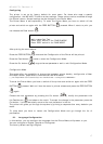
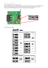
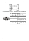
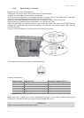
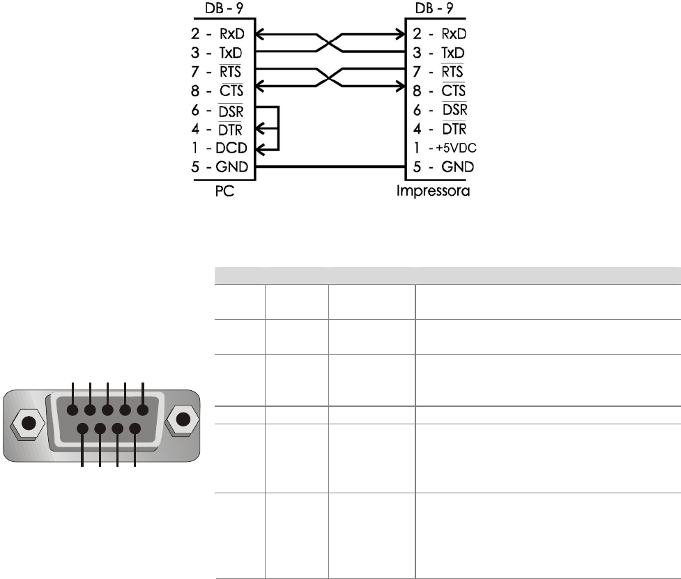
30. Cable Connection
Here you can see the Cable connections for both connectors; the pins are compatible with an
IBM-PC.
Pin Signal
Direction
Description
1
RING
Ind.
Output Power Supply (+5 VDC)
2 RxD Input
Data reception. The data for the
printer will be received in this pin.
3 TxD Output
Data transmission. The data from
the printer will be transmitted in
this pin.
5 GND - - - DC ground.
7 RTS Input
Request to send. If the level is low,
the printer can receive data. If the
level is high, the printer can’t
receive data.
5 4 3 2 1
9 8 7 6
8 CTS Output
Clear to send. If the level is low,
the printer can receive data. If the
level is high, the printer stops
sending data, if it is receiving at the
same time.