


RTC - 72421 / 72423
Page - 12 MQ - 162 - 03
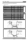
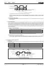
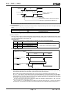
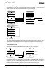
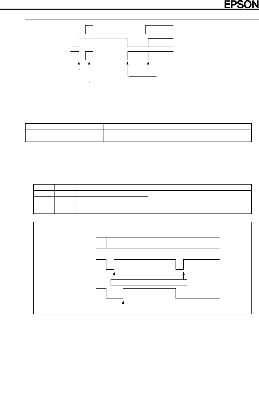
2.Fixed-period interrupt mode (ITRPT/STND=1)
1
1
1
0
0
0
0
Nothing is output because
the MASK bit is at 1
Interrupt timing
Reset at the point at which 0 is written to the IRF FLAG bit
No interrupts are generated while the MASK bit is at 1
*STD. P pin
IRQ FLAG bit
MASK bit
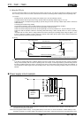
The output levels of the STD.P pin are low(down) and open circuit(up).
(2) ITRPT/STND bit (D1)
The ITRPT/STND bit specifies fixed-period pulse output mode or fixed-period interrupt mode for the fixed-period operating
mode.
The mode selected by each setting of this bit is as follows:
ITRPT/STND Operating mode
0 Fixed-period pulse output mode
1 Fixed-period interrupt mode
For details of the timing of fixed-period operation, see the section on the t0 and t1 bits below.
(3) t0 (D2), t1 (D3) bits
These bits select the timing of fixed-period operation in fixed-period pulse output mode or fixed-period interrupt mode. There
is no special counter within the RTC for fixed-period operation; the fixed-period operation is performed at the incrementation
of the time (period) specified by the t0 and t1 bits.
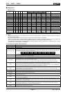
i. Setting t0 and t1
Setting these bits specifies the generation timing for fixed-period pulse output or fixed-period interrupts.
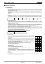
t1 t0 Period(frequency) Remarks
0 0 1/64 seconds (64 Hz)
0 1 1 second (1 Hz)
1 0 1 minute (1/60 Hz)
1 1 1 hour (1/3600 Hz)
In fixed-period pulse output mode, the STD.P pin output is low
for 7.8125 ms
(not that half the 1/64 second period is 7.8125 ms)
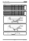
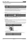
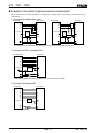
ii. STD.P pin output control
The timing of STD.P pin output is at the incrementation of the period specified by the t0 and t1 bits.
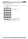
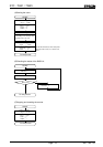
Example : STD.P pin output when 1 hour is set
(Conditions: t0=1, t1=1, MASK=0)
Fixed-period pulse output mode
Automatic reset after 7.8125 ms
Reset by writing 0 to IRQ FLAG bit
(ITRPT/STND=0)
(ITRPT/STND=1)
Fixed-period interrupt output mode
PM 1:00 PM 2:00
STD.P pin output
STD.P pin output
iii. Frequency of STD.P pin output in fixed-period pulse output mode
In fixed-period pulse output mode, the timing of output is determined by the frequency of the internal crystal unit. This
means that the output can be used to measure any error in the frequency of the crystal unit.
Note: The 30-seconds correction could generate a carry. If such a carry occurs when the t0 and t1 bits are set to
(0, 1) or (1, 1), the STD.P pin output could end up low. If the ITRPT/STND bit is 0, this low-level STD.P pin output will be
held from the time that the part of the counter that is below one second is cleared by the 30-seconds correction until the
incrementation of the 1/64-second digit of the internal counter restarts. Note that this may be different from the normal
case in which the STD.P pin output is low for 7.8125 ms.
The time of the low-level output of the first STD.P pin output after a RESET or STOP operation, or after 1 has been
written to the IRQ FLAG bit, may not be 7.8125 ms.
If any one of the t0, t1, or ITRPT/STND bits is overwritten, the IRQ FLAG bit may become 1. Therefore, after writing to
any of these bits, it is necessary to first write 0 to the IRQ FLAG bit then wait until the IRQ FLAG bit changes back to 1.