


Communications Interface
39 LRP2000 Passive Reader/Writer
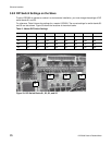
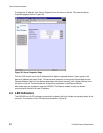
4.1.3 Digital Board DIP Switch
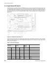
The digital board is mounted inside the LRP2000 enclosure closest to the wall with the cable entries. The
first five switches of the main board set the COM1 baud rate, electrical interface, and the download options
for COM2. SW6, SW7 and SW8 are not used and should remain OFF. When SW1 and SW2 are both set
ON, the baud rate is set via the Configuration Menu. Table 12 lists the possible switch settings for typical
applications.
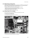
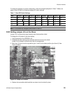
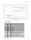
Figure 35: Configuration Dip Switch, S1
Figure 35 shows the location of the digital board dip switches, and hardware reset switch. It also includes a
detail view of the dip switch array, which indicates the arrangement of the switches from left to right and the
“ON” and “OFF” directions.
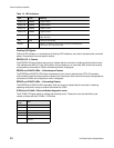
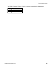
Table 12: Dip Switch Settings
Baud Rate Interface
Download/
Restore
Defaults
SW1 SW2 SW3 SW4 SW5 Settings
OFF OFF * * OFF 9600 BAUD
ON OFF * * OFF 19200
OFF ON * * OFF 38400
ON ON * * OFF Set from Configuration Menu
* * OFF OFF OFF RS232
* * ON OFF OFF RS422
IGNORED IGNORED IGNORED ON OFF Ethernet