


Operating Instructions
1. Install in a standard 19" rack or free-standing position.
2. Connect Power Distribution power cord into a 20 amp,
120 volt wall outlet (15 amp for Model PD11SS).
3. Plug sensitive electrical equipment into conditioned
outlets. All models have an additional protected outlet on
the front panel.
4. Move power outlet switch to "ON" position to provide
power to electrical equipment.
5. For illumination, pull out light tubes (PD11LP/LVP/LVSP)
and move light switch to "HI" or "LOW" position.
IMPORTANT! Be sure light switch is in "OFF"
position when light tubes are recessed.
6. Digital voltmeter readout (PD11VP/LVP/LVSP) is
calibrated to nominal 117V at the factory. No adjustment
necessary.
7. Digital voltmeter readout automatically displays
incoming voltage when power cord is connected.
Power Problems
Standard AC outlets often supply raw and unprocessed
power that not only can diminish the clarity of audio signals
and cause premature failure of parts, it can completely de-
stroy your valuable equipment.
Power problems such as spikes, line surges and noise
interference transmit through all standard electrical lines and
affect power quality: therefore, affecting you.
Solutions
Conditioned Power Distribution can eliminate such prob-
lems from affecting you. As it filters the line voltage from your
AC outlets, eliminating noise and interference, such as radio
frequency interference (RFI) and electromagnetic interfer-
ence (EMI), it will reduce the residual noise in the system,
which will enhance audio clarity.
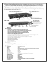
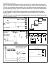
Installation Requirements
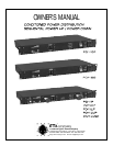
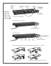
PD11P, PD11VP, PD11LP, PD11SP, PD11LVP, PD11LVSP
Plug unit into power source and observe status of four
"Protection" light emitting diodes. The (green) “1st Stage”,
“2nd Stage”, and “GROUND OK” L.E.D.’s should normally
be illuminated and the (red) “FAULT” L.E.D. should be off.
When these indications are present, test the power “On/Off”
switch which will illuminate to indicate that power is being
supplied to the switched outlets on the rear of the unit.
A. The “1st Stage” and “2nd Stage” L.E.D.’s indicate that
both the input (1st) and output (2nd) stages of circuit
protection are active.
B. The “GROUND OK” L.E.D. indicates that the chassis
is connected to the ground wire of the supply outlet.
C. Fault conditions are represented by the following
indications:
1
st
2
nd
Ground Fault
Stage Stage OK
(X) (X) (X) ( ) Supply circuit outlet wiring OK
( ) ( ) ( ) ( ) Open hot
( ) ( ) (X) (X)
Open Neutral
or
Hot & Ground Reversed
(X) (X) ( ) ( ) Open Ground
(X) (X) ( ) (X) Hot & Neutral Reversed
NOTE: (X) = “ON” ( ) = “OFF”
NOTE: On the PD11SS Model a green L.E.D. located on the
front panel is illuminated (indicating “Protection On” status)
when unit is plugged into a power source ensuring input and
output stages of circuit protection are active.
Audio Conditioned Power Distribution is also designed to
protect electronic equipment from potentially damaging high-
voltage spikes and surges.
Sequencing Audio Conditioned Power Distribution is de-
signed to initiate a turn-on cycle, energizing one circuit
immediately with remaining circuits energizing in a delayed
fashion. This allows circuits to stabilize when powering up and
down eliminating that on-rush of power and potential damage
to equipment at output receptacle.
6
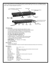
Programming Time Delays
The PD11SP, PD11SS and PD11LVSP come from the
factory set to a 1-second delay for each of the four outlets
to turn on. The following instruction will enable you to
change the amount of time between each outlet turn on.
•
The main power switch must be on
•
The sequenced outlets must not be active
• The switches to change the delay time are to left
of the unit and they have green L.E.D.s in the
switch.
• The switches are labeled POWER DOWN/UP
and OFF/ON PRESETS
• The POWER DOWN/OFF is the left switch
• The POWER UP/DOWN is the switch to the right
Programming Preset Time Delays
Step 1:
Depress and hold the DOWN/OFF switch
Step 2:
Depress and hold the UP/ON switch
Step 3:
Red L.E.D. to the right of the switches will
start to flash
Step 4:
When flashing red L.E.D. goes out, release
both switches
Step 5:
Both green L.E.D.s on the switches will start
to flash rapidly
Step 6:
You are in program mode at this time
Step 7:
The red L.E.D.s to the right indicate what the
time delay is set for:
L.E.D. 1 = 1 second delay
L.E.D. 2 = 5 second delay
L.E.D. 3 = 10 second delay
L.E.D. 4 = 30 second delay
Step 8:
Depress the UP/ON switch to the right to
increase the time delay
Step 9:
Depress the OFF/DOWN switch to the left to
decrease the time delay
Step 10:
Depress both OFF and ON switches to finish
the delay programming
Programming Manual Time Delays
Step 1:
Follow above instruction to activate L.E.D. 4
Step 2:
Depress the UP/ON switch one more time to
activate manual programming time delay
mode
Step 3:
All 4 red L.E.D.s to the right will be lit to
indicate manual mode
Step 4:
The UP/ON switch green L.E.D. will be lit
Step 5:
Depress the UP/ON switch to start manual
delay programming—can program from 5
sec. to 240 sec. delay
Step 6:
Depress the OFF/DOWN to stop the manual
delay timing
Step 7:
Depress both the OFF and ON switches to
finish programming mode