


Three-Wire Remote Control Interface
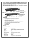
A three-wire remote control interface is added to the main PC board for the PD11SS, PD11SP AND PD11LVSP units. This remote control
interface is accessible through an external terminal block on the back of the unit (see Figure 6). This interface requires an external user provided
switch, L.E.D., and a three-wire cable to implement. The interface has been tested reliably over 1000 feet with 22-gauge speaker wire (see Figures
1 and 5).
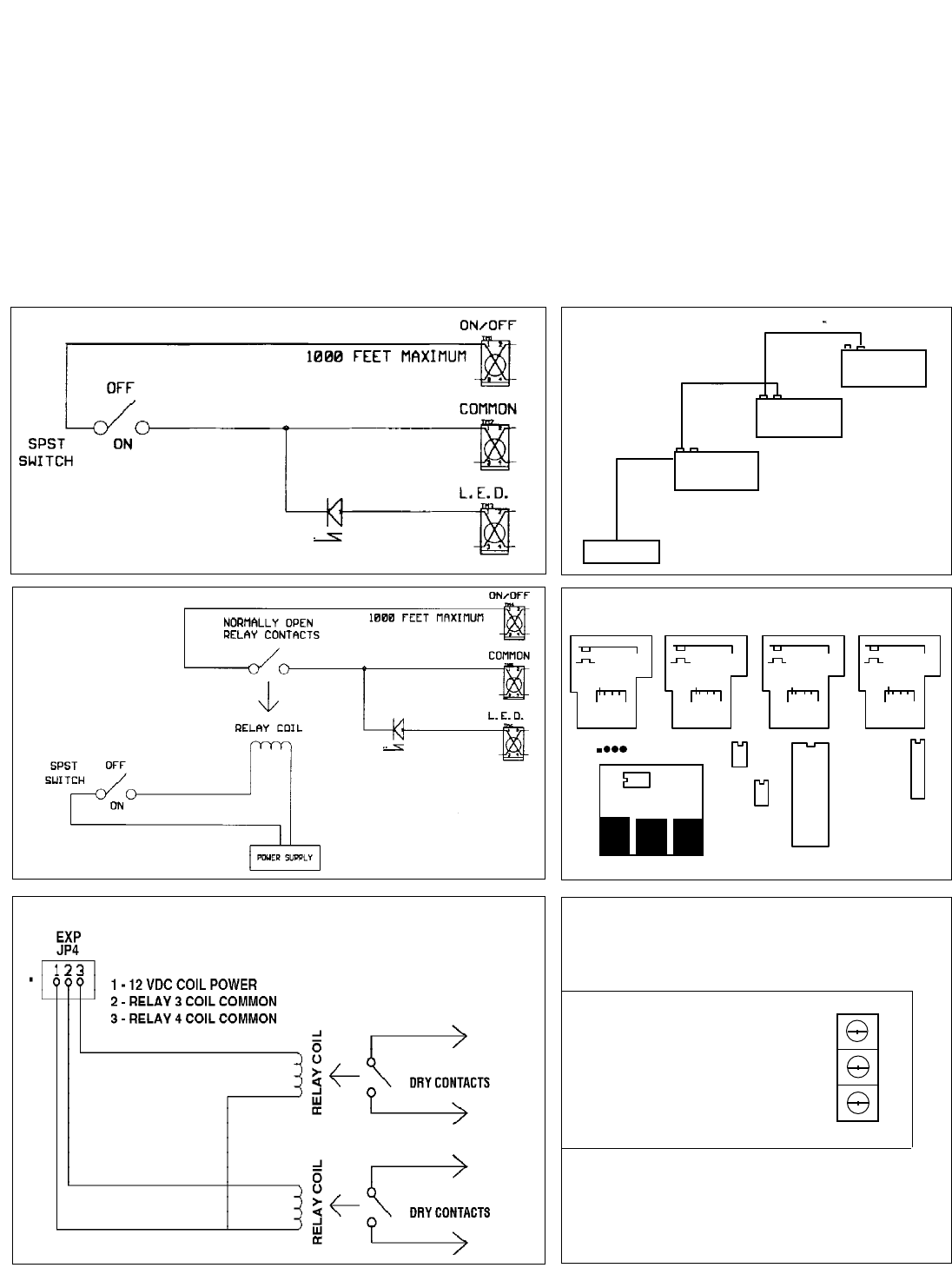
Connect the short minus (-) lead of the L.E.D. and one side of the switch to the COMMON terminal, the long plus (+) lead of the L.E.D. to the
L.E.D. terminal, and finally the other side of the switch to the ON/OFF terminal. When you close the switch, the L.E.D. will begin flashing until all
channels have sequenced ON, and then the L.E.D. will remain ON. When you open the switch the L.E.D. will begin flashing until all channels have
sequenced OFF and then the L.E.D. will remain OFF.
Remote Relay Function Operation (optional)
Using a set of relay contacts that are normally open instead of a switch you can control the PD11SS, PD11SP AND PD11LVSP units with a
relay. When you apply power to the relay the channels will sequence ON, and when you disconnect power from the relay the channels will
sequence OFF. This allows you to interface a PD11SS, PD11SP AND PD11LVSP unit with other equipment that has dry (normally open) relay
contacts (see Figure 2).
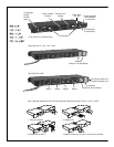
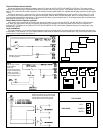
Larger Installations
In a larger installation, you can control different equipment racks from a remote location by running three-wire cable from each rack back to the
remote location. Then attach an L.E.D. and switch as before, these would be mounted in the user's control panel, and you now have remote control
of each rack in a single location (see Figure 3).
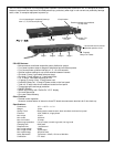
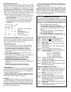
Standard use of 3-wire interface with L.E.D.
over 22 gauge wire.
Use of relay to control
3-wire interface
and L.E.D.
Can be used to extend
range of control beyond
1000 ft. or to control
3-wire interface from an
external voltage source.
Expansion connector for use with external
relays to provide dry contacts for channels
3 and 4. Relay coils should be 12V DC
and not draw more than 100 milliamps.
Fig. 1
Fig. 2
Fig. 3
Fig. 4
Fig. 5
Fig. 6
TOP OF CASE
L.E.D
COMMON
SWITCH
REAR PANEL