


EVGA 5
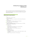
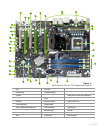
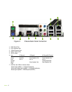
Figure 1.
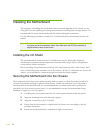
EVGA nForce 780i SLI FTW Motherboard Layout
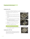
1. CPU Socket – For use with Intel LGA 775
CPUs
11. USB headers – for additional USB
connectors.
21. SPDIF connector – Digital Audio connection
2. NVIDIA SPP with Active fan – Also known as
the Northbridge
12. Motherboard battery – helps retain
system BIOS settings
22. PCI slots – Used for PCI based components
3. CPU fan connector – Connect CPU Fan to this
connector.
13. Fan connector
23. PCI Express x16 slots (SLI) – For graphics cards,
multiple slots are used for SLI configurations
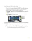
4. DDR DIMM Slots 0 – 3 – For System Memory
14. Serial connector – for Serial Port
dongal
24. 1394a connector – Firewire connection
5. 24-pin ATX Power Connector – Main Power
connection
15. Front panel connector – For use
with system chassis
25. PCI Express x1 slot – Exclusive for devices that
require a PCI-E x1 slot
6. IDE Connector – For IDE devices, CD-ROM
and Hard Disk Drives
16. CMOS Clear – Easily clears the
system the BIOS.
26. Back panel connectors – See Figure 2
7. Serial-ATA (SATA) connectors – For SATA
devices, CD-ROM and Hard Disk Drives
17. Power button – with integrated
power LED indicator
27. PWM / Voltage Regulator Heatsink – Aids in
dispersing heat
8. FDD connector – Floppy Disk Drive Connector
18. Reset Button – With integrated
HDD activity light.
28. 8-pin ATX 12V power connector – CPU 8-Pin Power
connector
9. NVIDIA MCP (passive heat sink)
19. Azalia HD Audio Header
29. MCP/SPP fan connector
10. System Speaker – Provides POST Codes via
audio
20. Front Panel Audio – For use with
system chassis
30. LED POST Code Readout – See Appendix A. For
Code descriptions
10
13
7
30
18
2
1
4
3
5
7
8
9
6
13
14
15
16
22
23
22
25
23
26
28
11
12
20
23
24
17
13
13
27
29
21
19