


EVGA 17
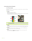
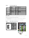
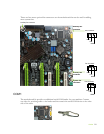
Table 2. Front Panel Header Pins
Pin
Signal
In/Out
Description
HD_LED
1
HD_PWR
Out
Hard disk drive LED pulls up to +5V
3
HDA#
Out
Hard disk drive active LED
PWRLED
2
HDR_BLNK_GRN
Out
Front panel green light
4
HDR_BLNK_YEL
Out
Front panel yellow light
RESET
5
GND
Ground
7
FP_RESET#
In
Reset switch
PWRSW
6
SWITCH_ON#
In
Power switch
8
GND
Ground
No Connect
9
No Connect
Empty
10
Empty
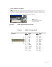
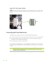
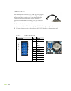
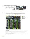
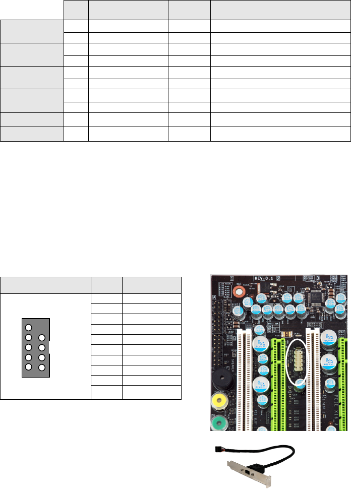
IEEE 1394a
The IEEE 1394a expansion cable bracket is provided in the box but if you do not require the
additional external connections, you do not need to install it.
1. Secure the bracket to either the front or rear panel of your chassis (not all chassis are equipped with
the front panel option).
2. Connect the two ends of the cables to the IEEE 1394a connectors on the motherboard.
Table 3. IEEE 1394a Connector Pins
Connector
Pin
Signal
IEEE 1394a Connector
1
TPA+
2
TPA-
3
GND
4
GND
5
TPB+
6
TPB-
7
+12V
8
+12V
9
Empty
10
GND
10
8
6
4
2
9
7
5
3
1