


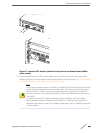
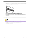
5 Secure the XENPAK module to the I/O module or option card by turning the two captive screws
clockwise until the screws are hand-tight.
Note
To ensure that your XENPAK module is undamaged upon installation, you can correlate
factory test data with your installation site test data by consulting the average power
reference values shown on the XENPAK module test data sheet (Part No. 121074-00)
enclosed with your module.
Remove a XENPAK Module
1 Disconnect the optical cable from the XENPAK module.
Warning
XENPAK modules contain Class 1 lasers. Invisible laser radiation can occur when laser
connections are unplugged. Do not stare into the beam.
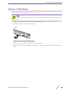
2 Loosen the two captive screws until they are completely free from the I/O module faceplate or the
Summit option card.
The captive screws remain attached to the XENPAK module.
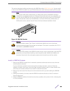
3 Gripping both captive screws, carefully pull the XENPAK module out of the slot.
4 Place the dust covers back into the XENPAK module connectors.
5 Place the XENPAK module immediately into an antistatic container to protect it from ESD damage
and dust.
Extreme Networks XENPAK Transceivers
Pluggable Hardware Installation Guide 48