


Installing a CFP2 Module
You can install or remove CFP2 modules in your switch without powering off the system.
Warning
CFP2 modules contain Class 1M lasers. Invisible laser radiation can occur when laser
connections areunplugged. Do not stare into the beam. This device is compliant with IEC
60825-1 Amendment 2 and CFR21Section 1040.
1 Remove the CFP2 module from its antistatic container and remove the dust covers from the module
optical connector.
If your module has a protective pad covering the card-edge connector, remove it. Store the
antistatic container, dust covers, and card-edge connector protective pad in a clean location from
which they can be easily retrieved if you need to uninstall the module.
2 Remove any rubber dust covers from the port where you are installing the CFP2 module.
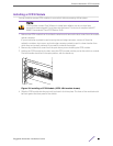
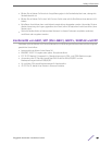
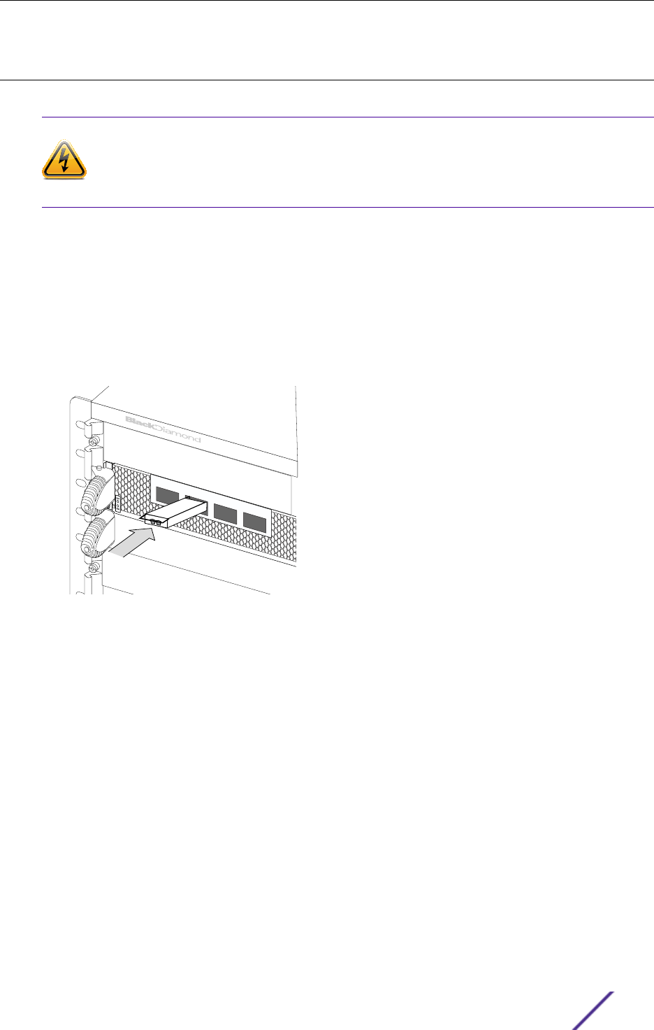
3 Holding the CFP2 module by its sides, insert the CFP2 module into the port on the switch or module.
The latch handle should be in the open position, with the handle up.
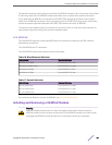
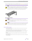
Figure 22: Installing a CFP2 Module (CFP2 LR4 module shown)
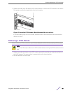
4 Slide the CFP2 module into the port until you hear it click into place. The front of the module should
be flush against the front panel of the chassis.
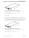
Extreme Networks CFP2 modules
Pluggable Hardware Installation Guide 51