


Cable Cubby 300/600/800 • Maintenance and Modifications 17
2. If the Phillips head screws on the front and rear of the cubby are blocked by the table,
remove the cubby from the table (see “Removing and Replacing the Cable Cubby,”
steps 1 through 4, on page 12).
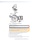
3. Before you add an additional power module, you must make room for the Cable Cubby
by eliminating two or three AAP spaces and the AAP shelf brackets that support them.
Remove the Phillips head screws on the front and rear of the Cable Cubby and gently
push the assembly(ies) out through the bottom of the cubby.
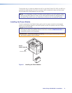
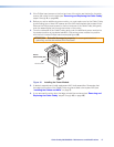
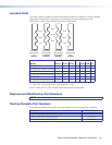
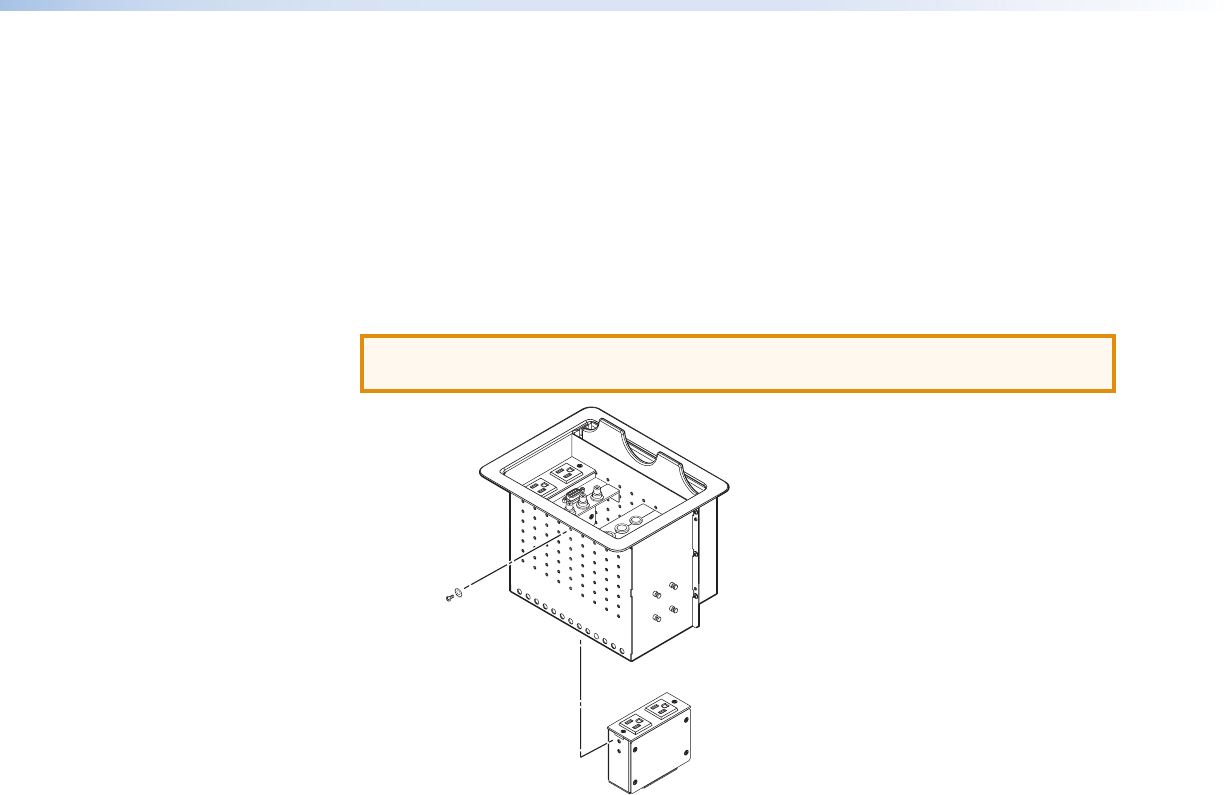
4. From the underside of the Cable Cubby, gently push the additional power module into
the desired position at the desired elevation. Secure the power module into position
with the four included Phillips head screws (see figure 16).
ATTENTION: Potential damage to property. To ensure good electrical
grounding, use the star washers with the screws.
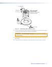
2 Screws ea. side
Extron
Cable Cubby 600
Figure 16. Installing the Power Module
5. If desired, assemble and install replacement AAP shelf assemblies. Remember that
the cable pull function of the Cable Cubby requires at least a two-space AAP (see
“Installing the Cables and AAPs” on page 7).
6. If you removed the cubby from the table, reinstall the enclosure (see “Removing and
Replacing the Cable Cubby” steps 7 through 10, on page 13).