


Cable Cubby 300/600/800 • Installation 4
Installation
This section covers the following topics:
• Installation Overview
• Preparing the Routing Template
• Preparing the Table
• Installing the Cables and AAPs
• Mounting the Cable Cubby
Installation Overview
Install and set up the Cable Cubby enclosures as follows:
1. If you plan to use a mounting template that has not been prepared, prepare the
template (see “Preparing the Routing Template” below).
2. Cut a hole in the surface where the enclosure will be installed (see “Preparing the
Table” on the next page).
3. Run all cables necessary to support the AC connector, the cables stored in the cubby,
and all planned AAP connectors. Leave enough slack in the cables to connect or route
them before the cubby is installed in the table.
4. If applicable, install the power module. If your location requires electrical conduit, install
an Extron flexible conduit kit. Refer to the Flexible Conduit Kit Installation Guide, Extron
part number 68-734-01.
5. Install all desired cables into the cable pass-through (split) AAPs and install the AAPs
into the Cable Cubby (see “Installing the Cables and AAPs” on page 7).
6. If applicable, connect cables to the rear connectors on the passive AAPs and install the
AAPs in the cubby (see “Installing the AAPs” on page 10).
7. Mount the Cable Cubby in the table (see “Mounting the Cable Cubby” on page 10).
8. Peel the protective film from the top surface.
9. Connect the Cable Cubby power cord.
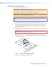
Preparing the Routing Template
Extron offers metal templates for each Cable Cubby model; see “Routing Template Part
Numbers” on page 19 for part numbers. Extron recommends using this template as a
guide to cut the hole in the table where the cubby will be installed.
NOTE: The metal routing template is reusable. Do not discard this template when the
installation is complete. Save it for installing Cable Cubby models of the same size.
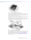
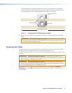
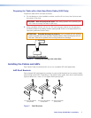
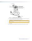
1. Cut 1/2 inch x 4 inch strips of soft, finished lumber to a length that is long enough to
span the distance between the desired installation location on the mounting surface and
the edges of the mounting surface (see figure 4).