


Installation, cont’d
CrossPoint Matrix Switchers • Installation2-4
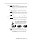
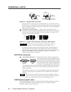
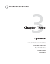
Tip (+)
Sleeve ( )
Sleeve ( )
Ring (
-
)
Tip (+)
RCA Connector
3.5 mm Stereo Plug Connector
(balanced)
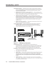
Figure 2-4 — Typical audio connectors
The audio level for each input can be individually set, via the front panel or
RS-232/422, to ensure that the level on the output does not vary from input to
input. See chapter 3, Operation, chapter 4, Programmer’s Guide, and chapter 5,
Matrix Software for details.
5
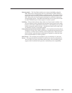
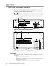
Connections for audio outputs — These 3.5 mm, 5-pole captive screw
connectors output the selected unamplified, line level audio. Connect audio
devices, such as an audio amplifier or powered speakers. See figure 2-5 to
properly wire an output connector.
Unbalanced Output
Tip
See caution
Sleeve
Tip
See caution
Balanced Output
Tip
Ring
Sleeve (s)
Tip
Ring
Figure 2-5 — Captive screw connector wiring for audio output
CAUTION
Connect the sleeve to ground (Gnd). Connecting the sleeve to a
negative (-) terminal will damage the audio output circuits.
By default, the audio output follows the video switch. Audio breakaway,
commanded via the front panel, under RS-232/422 control, or Windows-
based control program, allows you to select from any one of the audio input
sources. See chapter 3, Operation, chapter 4, Programmer’s Guide, and
chapter 5, Matrix Software for details.
RS-232/422 connection
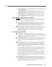
6
Remote/RS-232/422 port — Connect a host device, such as a computer or
touch panel control, to the CrossPoint via this
9-pin D connector for serial RS-232/422 control.
If desired, attach an MCP 1000 remote control
panel master unit to the switcher’s RS-232/422
connector. You can also attach an MKP 1000
remote keypad or MCP 1000 slave unit to the MCP 1000 master unit. Refer to
the MCP 1000 Remote Control Panel User’s Manual and the MKP 1000 User’s
Manual for details.
See chapter 4, Programmer’s Guide, for definitions of the SIS commands and
chapter 5, Matrix Software for details on how to install and use the control
software.
The CrossPoint Series Matrix Switchers are factory configured for RS-232
control. To use the switcher under RS-422 control, an internal cable must be
moved. See Appendix B for the procedure for shifting the cable.
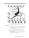
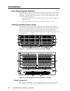
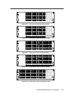
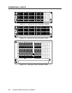
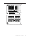
Additional rear panel views
The following figures show the rear panels of all CrossPoint switchers, except for
the CrossPoint 128HVA, which is shown in figure 2-1, and the CrossPoint
1616HVA, which is shown in figure 2-2.
Female
51
96
Male
15
69