Operation, cont’d
CrossPoint Matrix Switchers • Operation3-16
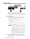
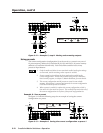
If another input button is pressed and released, the level value for the current
input is saved and level value for the newly selected input is displayed.
E
Press and release the Audio button. The Audio LED stops blinking and the
View (
) LED (if lit), the Esc ( ) LED (if lit), the selected input LED, and all
output LEDs turn off.
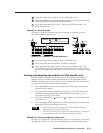
Both the RGBHV and Audio LEDs light.
Front panel security lockout (executive mode)
The front panel security lockout limits the operation of the CrossPoint switcher
from the front panel. When the switcher is locked, all of the front panel functions
are disabled except for the view-only mode functions. See Viewing a configuration
on page 3-8. Other than in view-only mode, if the user pushes a front panel button
when the switcher is locked, that button’s associated LED flashes twice and goes
out.
To toggle the security lockout on or off, press and hold the RGBHV and Audio
buttons for approximately two seconds. The RGBHV and Audio LEDs blink twice
to indicate the mode change. Release the RGBHV and Audio buttons. To toggle
the lockout state again, press and hold the RGBHV and Audio buttons again.
System reset to factory defaults
To reset the switcher to the factory default settings, press and hold the Esc button
on the front panel while AC power is being applied. Continue to hold the Esc
button until the power up sequence is completed (all LEDs turn off, the Video and
Audio LEDs turn on, the Esc LED blinks, and the Power LED (if equipped) turns
on). System reset clears all ties and presets and sets all audio gain levels to unity
gain (+0dB).
Rear Panel Controls
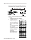
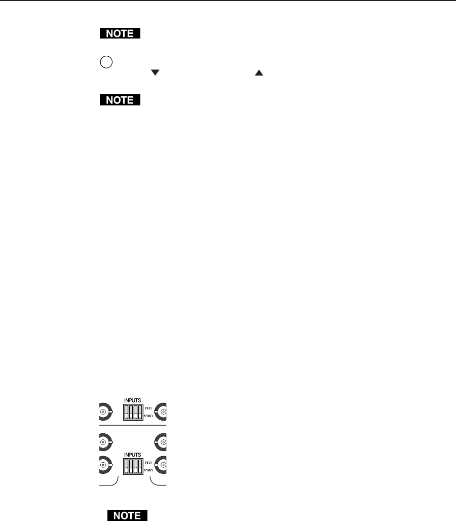
The CrossPoint 168 and 1616 have sync termination switches on the rear panel for
inputs 1, 3, 5, and 7. The switches provide a way to condition
non-TTL sync levels greater than 5 Vp-p, enabling the sync to be
properly passed from input to selected output(s). The
CrossPoints have two sets of sync termination switches; one for
horizontal or combined sync and a second set for vertical sync.
Each switch provides the option of selecting either 510 ohms or
75 ohms. The 75 ohms position is required only for an input
with non-TTL sync, greater than 5V p-p. The normal position is
510 ohms.
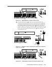
An input that produces an out-of-sync display, a display that is rolling
vertically and/or tearing horizontally, could indicate a non-TTL sync input. A
device is known to output non-TTL sync levels (greater than 5V p-p) should be
connected to one of the inputs with sync termination, and the termination
switches for that input should be set to the 75 ohm position. If you’re not sure,
check the specifications in the user’s manual for the input device.
Troubleshooting
This paragraph gives recommendations on what to do if you have problems
operating the CrossPoint, and it provides examples and descriptions for some
image problems you may encounter.
16
15
16
135
7
135
7


