


30 DMS 1600, DMS 2000, DMS 3200, DMS 3600 • Maintenance and Modifications 31DMS 1600, DMS 2000, DMS 3200, DMS 3600 • Maintenance and Modifications
ANAHEIM, CA
RESET
REMOTE
RS-232/RS-422
LAN
BI-LEVEL
TRI-LEVEL
ACT LINK
100-240V 50/60Hz 1.2A MAX.
100-240V 50/60Hz 1.2A MAX.
REDUNDANT
PRIMARY
DISCONNECT BOTH POWER
CORDS BEFORE SERVICING
SWITCH
REFERENCE
PRIMARY POWER SUPPLY
REDUNDANT POWER SUPPLY
1 - 8
9 - 16
17 - 24
25 - 32
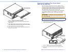
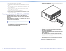
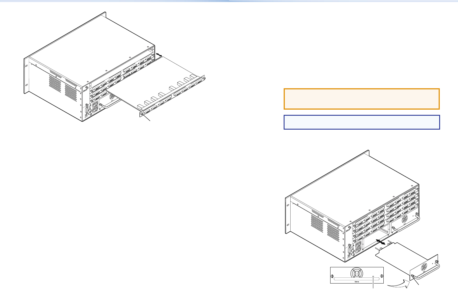
Align the board edges
with the plastic guides.
A
B
DVI-D INPUTS DVI-D OUTPUTS
DMS 44 DVI
C D A B C D
A
B
DVI-D INPUTS
DVI-D OUTPUTS
DMS 44 DVI
C D A B
C
D
A B
DVI-D INPUTS DVI-D OUTPUTS
DMS 44 DVI
C D A B
C
D
IN
A B
DVI-D INPUTS
DVI-D OUTPUTS
DMS 44 DVI
C D A B C D
Knurled Knobs
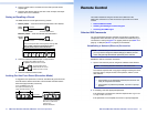
Figure 14. Remove and Install an I/O Board
7. For an I/O board, align the board with the left and right chassis
guides (above).
8. Gently slide the board or blank panel into the enclosure. For an I/O
board, slide the board toward the front panel until it meets resistance.
9. Gently seat the board or panel in the backplane.
10. Use a screwdriver to tighten the left and right knurled knobs to lock
the board or panel in place.
Removing and Installing a Power Supply Module
(DMS 1600 and DMS 3600)
Each power supply module has a two-color LED, visible on the rear
panel, that indicates the status of the power supply outputs. If the LED
is lit green, the power supply is operating normally. If the LED is lit red,
the supply has failed and should be replaced at the earliest opportunity.
LEDs with identical meanings are also on the front panel.
The two power supply modules (primary power supply and redundant
power supply) are identical and hot-swappable; you do not need to
power down the switcher to install or remove either power supply
module.
ATTENTION: The DMS matrix switchers use double pole/
neutral fusing. Power must be disconnected before servicing
internal components.
NOTE: DMS 2000 and DMS 3200 — The power supplies are xed
in place and are not eld replaceable.
1. Rotate the left and right knurled knobs to completely loosen the
captive screws (see gure 15).
Align the power
supply edges with
the plastic guides.
ANAHEIM, CA
RESET
REMOTE
RS-232/RS-422
LAN
BI-LEVEL
TRI-LEVEL
ACT LINK
100-240V 50/60Hz 1.2A MAX.
100-240V 50/60Hz 1.2A MAX.
REDUNDANT
PRIMARY
DISCONNECT BOTH POWER
CORDS BEFORE SERVICING
SWITCH
REFERENCE
PRIMARY POWER SUPPLY
REDUNDANT POWER SUPPLY
1 - 8
9 - 16
17 - 24
25 - 32
Knurled
Knobs
Power
LED
A B
DVI-D INPUTS DVI-D OUTPUTS
DMS 44 DVI
C D
A B C D
A
B
DVI-D INPUTS
DVI-D OUTPUTS
DMS 44 DVI
C D A B
C D
A
B
DVI-D INPUTS DVI-D OUTPUTS
DMS 44 DVI
C D A B C
D
A B
DVI-D INPUTS DVI-D OUTPUTS
DMS 44 DVI
C D
A B C D
Figure 15. Remove and Install a Power Supply Module
2. Gently pull on the handle to loosen the power supply from the
backplane.