


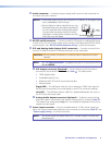
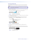
i Audio output connector — This 5-pole, 3.5 mm captive screw connector outputs
the transmitted, unamplified, line level analog audio. Connect an audio device, such as
an audio amplifier or powered speakers.
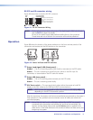
See figure 4 to properly wire a captive screw output connector. Use the supplied
tie-wrap to strap the audio cable to the extended tail of the connector.
Unbalanced Stereo Output Balanced Stereo Output
Do not tin the wires!
Tip
NO GROUND HERE
NO GROUND HERE
Tip
LR
Sleeves
Tip
Ring
Tip
Ring
LR
Figure 4. Captive Screw Connector Wiring for Stereo Audio Output
CAUTION: For unbalanced audio, connect the sleeves to the ground contact.
DO NOT connect the sleeves to the negative (-) contacts.
NOTE: The length of exposed wires is critical. The ideal length is 3/16 inch (5 mm).
• If the stripped section of wire is longer than 3/16 inch, the exposed
wires may touch, causing a short circuit.
• If the stripped section of wire is shorter than 3/16 inch, wires can be
easily pulled out even if tightly fastened by the captive screws.
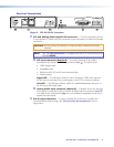
j RS-232 and IR connector — Connect a serial RS-232 signal, a modulated IR signal,
or both to this 3.5 mm, 5-pole captive screw connector for bidirectional RS-232 and IR
communication. See “RS-232 and IR connector wiring“ to wire the connector.
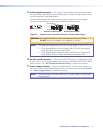
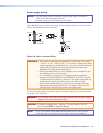
k Power input connector — Plug the included external 12 VDC power supply into
either this 2-pole connector or the power input connector on the transmitter (item
f
).
See “Power supply wiring“ to wire the connector.
NOTE: One power supply can power both units. A power supply is included with
the transmitter.
DTP DVI 301 • Installation and Operation 6