


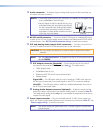
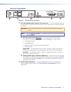
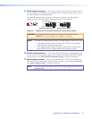
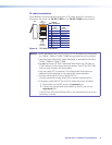
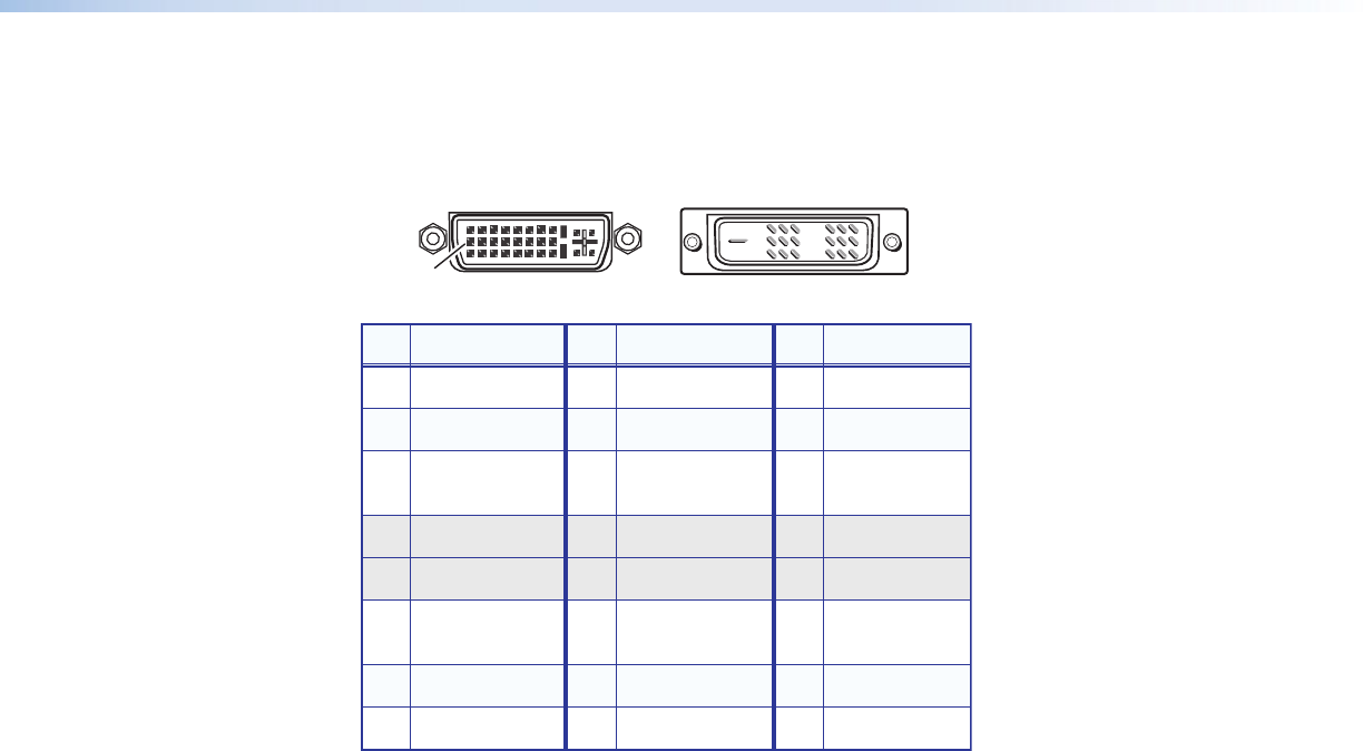
Pin Assignments and Wiring
DVI connector pin assignments
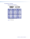
Figure 5 defines the pinout for the DVI connector.
Pin Signal
1
TMDS data 2–
TMDS data 2+
TMDS data 1–
TMDS data 1+
DDC clock +5 V power
DDC data TMDS clock+ Ground (+5 V)
CEC control* TMDS clock– Hot Plug Detect
TMDS data 0–
TMDS data 0+
Spare
Spare
Spare
Spare
Spare
Spare
TMDS data 2
shield
TMDS data 1
shield
TMDS data 0
shield
TMDS clock
shield
Pin Pin Signal Signal
2
9
10
17
4 12 20
5 13 21
6 14 22
7 15 23
8
* CEC control on pin 8 is a proprietary usage,
not the industry standard.
16 24
18
3 11 19
9
17 24
Female Connector
Male Connector
Figure 5. DVI Connector
DTP DVI 301 • Installation and Operation 7