


Installation and
Operation
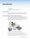
This section describes the installation and the operation of the DTP DVI 301 Tx/Rx Extender,
including:
• Mounting the Transmitter or Receiver
• Connections
• Operation
Mounting the Transmitter or Receiver
CAUTION: Installation and service must be performed by authorized personnel only.
Mounting instructions and the applicable optional hardware can be found in the
“Reference Information“ section. The 1-inch high, quarter rack width DTP DVI 301
transmitter or receiver can be placed on a tabletop, mounted on a rack shelf, or mounted
under a desk or tabletop. The receiver can also be mounted on a projector bracket.
Connections
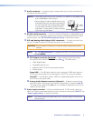
Transmitter Connections
.
INPUTS
LOCAL OUTPUT
AUDIO
DVI-D
DTP DVI 301 Tx
RxTx
RS-232 IR
RxTx
LOCAL
SPARE
REMOTE
1 2
ON
DDC ROUTE
POWER
12V
0.7 A MAX
OUT
ANALOG AUDIO
SIG LINK
DTP OUT
FrontRear
4
6 1 3 2
5
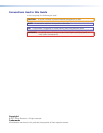
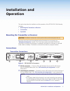
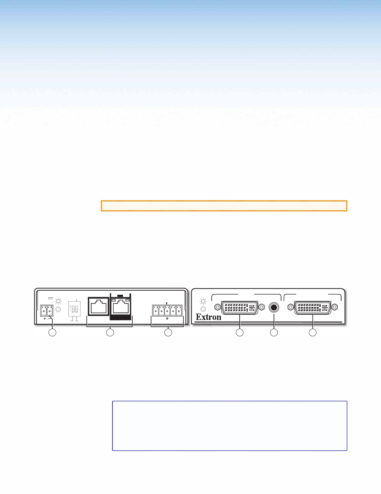
Figure 2. DTP DVI 301 Tx Connectors
a DVI-D connector — Connect a DVI cable between this port and the DVI output
port of the digital video source. See “DVI connector pin assignments“ for pin
assignments.
b Local Output connector — If desired, connect a DVI monitor for local monitoring of
the input digital image. See “DVI connector pin assignments“ for pin assignments.
NOTES: • The local output is limited to a data rate of 4.95 Gbps (1.65 Gbps per
color).
• In a system where the local output is not used, ensure that you power up
the end display first before the video source. Route the DDC to the remote
end (see the DDC Route DIP switch [see item
c
, in the “Operation”
section]).
DTP DVI 301 • Installation and Operation 3