


DTP T HWP/UWP 232/332 D Transmitters • Remote Control 18
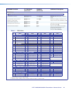
Using the Command and Response Table
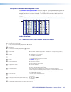
The command and response table begins on page 20. Symbols are used throughout the
table to represent variables in the command and response fields. Command and response
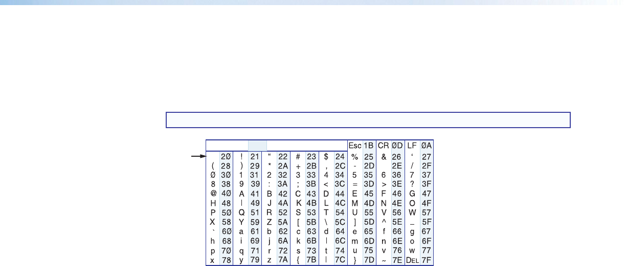
examples are shown throughout the table. The ASCII to HEX conversion table below is for
use with the command and response table.
NOTE: Upper and lowercase text can be used interchangeably unless otherwise stated.
ASCII to Hex Conversion Table
•
Space
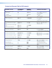
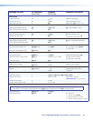
Symbol definitions
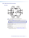
DTP T HWP 232/332 D and DTP UWP 232/332 D models
]
= Carriage return/line feed
}
= Carriage return (no line feed)
| = Pipe (can be used interchangeably with the
}
character)
• = Space
E
= Escape key
W = Can be used interchangeably with the
E
character
X! = Input number 0
through
2
(
0
= deselect input [break tie]. This results in the output being disabled.)
1 = HDMI, 2 = VGA (UWP models)
X@ = Status 0 = off, disabled, or not detected
1 = on, enabled, or detected
X# = Auto switch mode 0 = disabled (default)
1 = enabled (highest active input has priority)
X$ = EDID See table 1 on page 22.
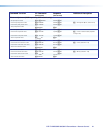
X% = Input HDCP status 0 = No source is detected
1 = Source is detected with HDCP
2 = Source detected without HDCP
X^ = Output HDCP status 0 = No sink is detected
1 = Sink is detected with HDCP support
2 = Sink is detected without HDCP support
X& = Transmitter name A text string of up to 24 alphanumeric characters and minus sign/hyphen (-).
No blank or space characters are permitted as part of a name. The first letter must a
letter, and the last character must not be a minus sign/hyphen (default is
DTP-T-HWP/UWP-232/332).
X* = Raw EDID data 128 or 256 bytes of hexadecimal data
X( = Video color bit depth mode 0 = Auto (default, based on sink EDID)
1 = force 8-bit
X1) = Analog input video format (UWP models only) 0 = Auto detect (default)
1 = RGB/VGA
2 = YUV/component video
X1! = Current EDID native resolutions and refresh rate in plain text