


DTP T HWP/UWP 232/332 D Transmitters • Introduction 1
Introduction
• About this Guide
• About the DTP T HWP D and DTP T UWP D Extenders
• Features
About this Guide
This guide provides instructions for experienced, professional installers to install, operate,
and configure the Extron DTP T HWP D and DTP T UWP D family of High-Definition
Multimedia Interface (HDMI
®
) and VGA Extenders.
Terms Used in this Guide
The terms “extender” and “transmitter” are used interchangeably in this guide to refer to all
of the DTP T HWP D and DTP T UWP D models.
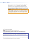
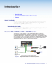
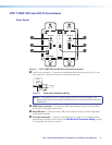
About the DTP T HWP D and DTP T UWP D Extenders
The Extron DTP T HWP D and DTP T UWP D extenders are a family of HDMI and
VGA transmitters (see figure 1) that are housed in enclosures that can be mounted in
Underwriters Laboratories (UL
®
) standard wall boxes with Decora
®
-style faceplates. Paired
with a compatible DTP 230 or 330 receiver, they extend the usable distance of HDMI digital
video, VGA analog video (UWP models only), and RS-232 or IR control signals over one
shielded twisted pair (STP) cable. The extenders also route audio.
AUTO SW
CONFIG
IR OUT
HDMI IN
AUDIO IN
S
G
HDCP
1
HDMI IN
AUDIO IN
HDCP
1
2
AUTO SW
CONFIG
IR OUT
HDMI IN
AUDIO IN
S
G
HDCP
1
AUDIO IN
VGA IN
TLP 1000TV
IPCP 505
IN1608
DTP HDMI 230 Rx
Projector
100-240V ~ -- A MAX
1
2
CONFIGURABLE
HDMI
HDMI
5
6
7
8
C
RS-232IR
RS-232IR
Tx Rx Tx RxG
Tx Rx Tx RxG
Tx Rx Tx RxG
HDMI
A
B
3
4
INPUTS
OUTPUTS
Tx Rx
RS-232
G
LAN
2x25W(8Ω)/2x50W(4Ω)
RESET
AUDIO INPUTS
OUTPUTS
REMOTE
LL1R R
L2
R
L
3
R
CLASS 2 WIRING
L4
R
L5R
+48V
+48V
12
LR
VARIABLE
IN1608 SA
2
MIC/LINE
L6
R
SIG LINK
DTP IN
SIG LINK
DTP IN
SIG LINK
DTP OUT
50/60 Hz
RS-232IR
OVER DTP
OVER DTP
OVER DTP
AMPLIFIED OUTPUT
VOLUME
SCALING PRESENTATION SWITCHER
IN1608
INPUTS
1
HDCP
SIGNAL
OUTPUTS
ENTER
MENU
Extron
2 3 4 5 6 7 8 A B C
INPUTS
1 2 3 4 5 6 7 8
CONFIG
Extron
DTP T UWP 232 D Tx
Transmitter
Extron
DTP T HWP 232 D Tx
Transmitter
Ethernet
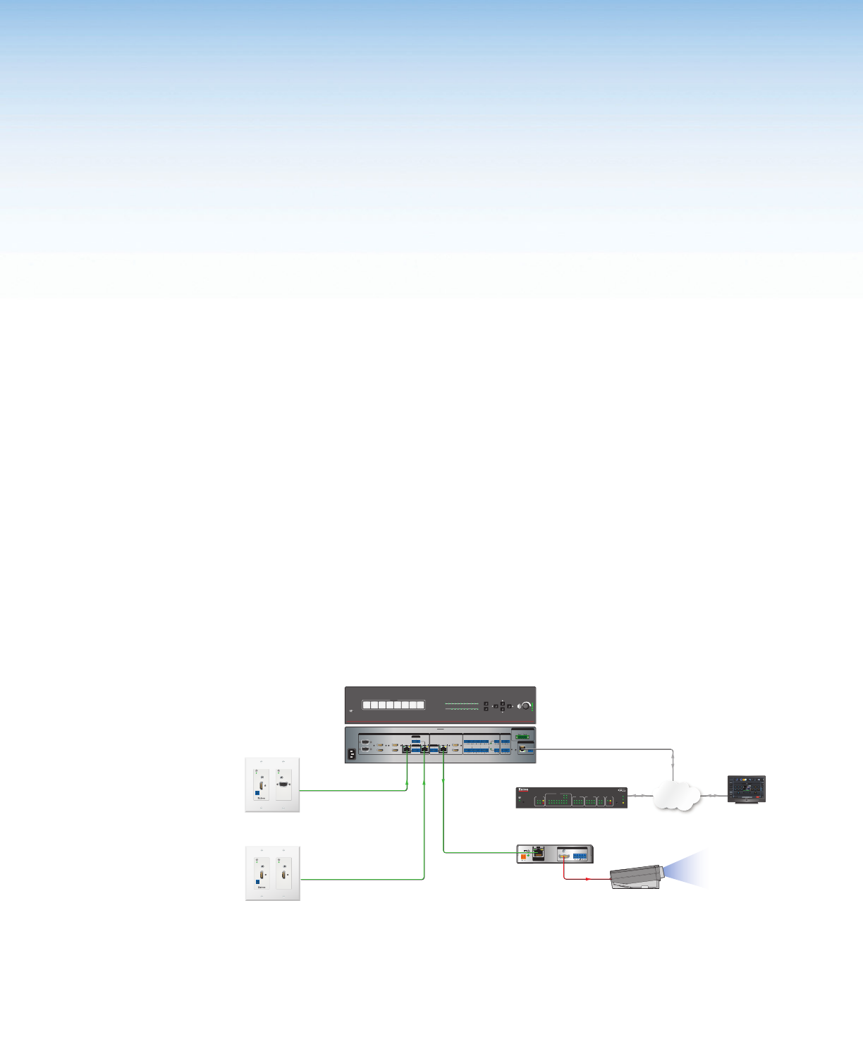
A Typical DTP T HWP 232 D and DTP T UWP 232 D Application
Network
LR
POWER
12V
0.7A MAX
AUDIO
SIG LINK
DTP IN
OUTPUTS
XTP DTP 24 Cable
230 '
XTP DTP 24 Cable
230 '
XTP DTP 24 Cable
230 '
HDMI
1 2345678
100
LINK
ACT
COM
IR/S
TX
RX
TX
RX
RTS
CTS
R
5
1
6
2
7
3
8
4
RELAY
FLEX
I/O
5
1
6
2
3
1
4
2
eBUS
ACT LIMIT
OVER
SWITCHED
12VDC
3
1
4
OVER
2
LIMIT
IR
7
3
8
4
IPCP 505
Figure 1. A Typical Transmitter and Receiver Application