


DVI-RGB 150 • Installation and Operation
Installation and Operation, cont’d
2-10
DVI-RGB 150
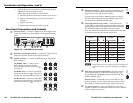
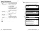
DVI Connector Pin Assignments
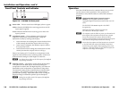
Figure 2-7 and the table below defi ne the DVI pin assignments.
1
9
8
17 24
81
24 17
Female Connector
Male Connector
Figure 2-7 — DVI connectors
DVI signals run at a very high frequency and are especially
prone to bad video connections, too many adapters, or excessive
cable length. To avoid the loss of an image or jitter, follow these
guidelines:
• Do not exceed 16.4 feet (5 meters) on the input or buffered
loop-through of the interface.
• Use only the cable designed for DVI signals supplied by
Extron.
• Limit or avoid the use of adapters.
• Use only approved DVI connectors.
C
Use only cables specifi cally intended for DVI
interfaces. Use of non-DVI cables or modifi ed
cables can cause the DVI-RGB 150 to fail.
N
The missing connectors on the included DVI cable are not
required for the single link of DVI-D data supported by the
DVI-RGB 150. These pins are grayed out on the following
table.
Pin Pin PinSignal Signal Signal
19
2
TMDS Data 2- TMDS Data 1-
17
TMDS Data 0-
TMDS Data 2+ TMDS Data 1+ TMDS Data 0+
TMDS Data 4+ TMDS Data 3+ TMDS Data 5+
TMDS Data 4- TMDS Data 3- TMDS Data 5-
TMDS Data 2/4 TMDS Data 1/3 TMDS Data 0/5
10 18
3
Shield
11
Shield
19
Shield
41220
51321
6 DDC Clock 14 +5 V Power 22
TMDS Clock
Shield
7 DDC Data 15 Ground (+5 V) 23 TMDS Clock
8 No Connection 16 Hot Plug Detect 24 TMDS Clock
A
Appendix A
Reference Information
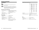
Specifi cations
Part Numbers