


HSA 822 Hideaway
®
Enclosure • Installation
HSA 822 Hideaway
®
Enclosure • Installation
Installation, cont’d
Cabling the Enclosure
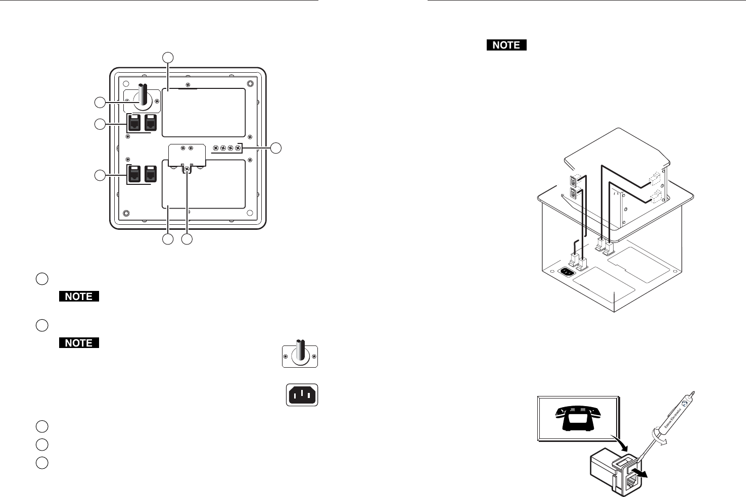
Bottom panel features
3
3 5
4
1
2
1
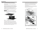
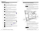
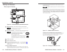
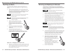
Figure 2-6 — HSA 822 enclosure underside connectors
1
RJ-45 connectors — See Cabling the RJ-45 connectors below.
All RJ-45 connectors are teminated in accordance with
the TIA/EIA 568 A standard.
2
AC power connector — Connect this cord to the power source.
For US-domestic versions, this power cord is
permanently connected to the HSA.
Connect the power cord to a 125 VAC,
60 Hz, 10 A power source.
For international versions, this power cord is a
removable IEC power cord. Connect the cord
to a 220-250 V, 50/60 Hz, 10 A power source.
3
Cable access holes
4
Spare AAP panel screws
5
Top panel height adjustment screw — See “Adjusting the
height of the top surface” in chapter 3, “Maintenance and
Modifications”.
Cabling the RJ-45 connectors
Plug one end of a CAT 5 or CAT 6 twisted pair (TP) cable into
each of these RJ-45 female connectors. Connect the other end to
2-10
an appropriate telecommunications or data network or to an
Extron TP product.
An RJ-11 (telephone) plug can be connected to the RJ-45
jack.
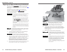
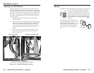
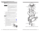
When cabling the AAP panels and the bottom panel, the bottom
RJ-45 connectors match up with the AAP panel RJ-45 connectors
as shown in figure 2-7. For example, match the AAP panel RJ-45
connector A1 with the underside RJ-45 connector A1, match A2
with A2, and so forth.
A1
A2
B1
B2
A1
A2
B1
B2
Figure 2-7 — HSA 822 RJ-45 connectors
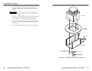
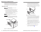
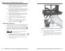
If necessary have a qualified service person replace the
connector icon on the AAP panel by prying the old icon off of
the connector plug-in with a tweeker or small screwdriver
(figure 2-8) and snapping a new icon in place.
Icon Labels
Figure 2-8 — Changing the connector icon
2-11