


IN1124/28/30 Transmission System • Quick Start Guide
Quick Start Guide — IN1124/1128/1130
Transmission System
Step 1
Turn the equipment off and disconnect the equipment from the
power source.
Step 2
If desired, rack mount the transmitter. Use the optional 1U rack-
mount shelf, part #IN9080, for rack mounting.
Step 3
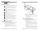
If desired, furniture mount the receiver. Use the optional mounting
brackets, part #IN9089, to mount the receiver to any flat surface.
Step 4
Video input — Connect the
VGA-UXGA RGBHV, RGBS, RGsB
video
input to the 15-pin HD Input connector on the transmitter.
Step 5
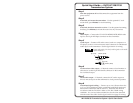
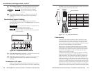
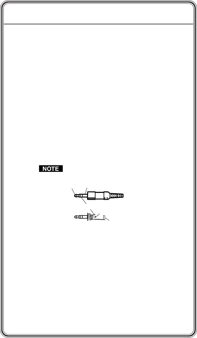
Audio input — Connect a PC audio source (such as a computer or a
CD player) to the 3.5 mm mini stereo audio connector for unbalanced
audio input on the transmitter. See the figure below for wiring.
Input only analog, line level, audio signals on the audio
input connector.
Tip (Left) Sleeve (Gnd)
Tip (Left)
Ring (Right)
Sleeve (Gnd)
Step 6
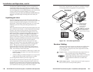
Local monitor video output — If desired, connect a local monitor or
other device to this 15-pin HD female connector on the transmitter
for a buffered output.
Step 7
Local audio output — If desired, connect the PC audio output on
this 3.5 mm stereo jack on the transmitter to local powered speakers.
Step 8
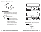
Transmitted signal cabling — Connect up to 4 or 8 Extron skew-free
A/V or CAT 5 (minimum) cables, terminated with RJ-45 connectors,
between the transmitter and all receivers. Terminate the cables in
accordance with the TIA/EIA T 568A or TIA/EIA T 568B wiring
standards. You can use either standard, but use the same standard
on both ends of the cable. See the figure on the next page for wiring.